
6
Installation Note
Agilent Technologies E5346A 38-Pin Probe and E5351A 38-Pin Adapter Cable
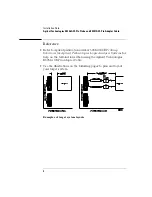
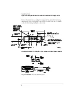
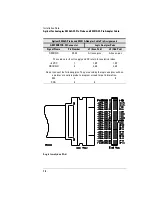
Notice the holes for mounting the support shrouds in the following
illustration. One of the holes is off center to allow 0.40 in. (1.02 mm)
centers when using multiple connectors.
Board pad details of 38-pin MICTOR connector and support shroud
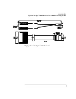
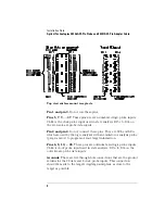
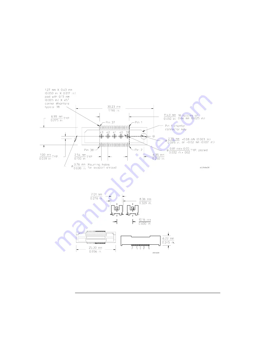
38-pin MICTOR connector dimensions


