background image


9

Installation Note

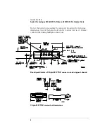
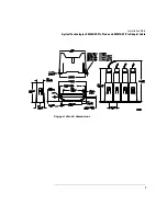
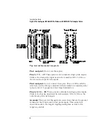
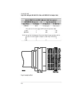
Agilent Technologies E5346A 38-Pin Probe and E5351A 38-Pin Adapter Cable

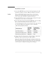
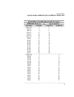
Agilent E5346A Probe and E5351A Adapter Cable Pin Assignments

AMP MICTOR-38 Connector

Logic Analyzer Pods

Signal Name

Pin Number

J1 (Even Pod)

J2 (Odd Pod)

CLOCK even

5

3

D15 even

7

7

D14 even

9

9

D13 even

11

11

D12 even

13

13

D11 even

15

15

D10 even

17

17

D9 even

19

19

D8 even

21

21

D7 even

23

23

D6 even

25

25

D5 even

27

27

D4 even

29

29

D3 even

31

31

D2 even

33

33

D1 even

35

35

D0 even

37

37

CLOCK odd

6

3

D15 odd

8

7

D14 odd

10

9

D13 odd

12

11

D12 odd

14

13

D11 odd

16

15

D10 odd

18

17

D9 odd

20

19

D8 odd

22

21

D7 odd

24

23

D6 odd

26

25

D5 odd

28

27

D4 odd

30

29

D3 odd

32

31

D2 odd

34

33

D1 odd

36

35

D0 odd

38

37

Summary of Contents for E5346A

Page 1: ...to a small area of a target system The Agilent Technologies E5346A probe has RCR isolation networks in the cable end that connects to the 38 pin AMP MICTOR Matched Impedance ConnecTOR connector The A...

Page 2: ...to select the part number of the correct shroud for your board thickness The kits listed consist of 5 MICTOR connectors and 5 support shrouds 4 Connect either the 38 pin probe or 38 pin adapter cable...

Page 3: ...7D 16710A 16711A 16712A 16715A 16716A 16717A 16718A 16719A 16750A 16751A or 16752A The following equivalent probe load diagram includes the logic analyzer and 38 pin MICTOR connector Equivalent probe...

Page 4: ...gilent publication number 5968 4632E Probing Solutions for Agilent Technologies Logic Analysis Systems for help on the terminations when using the Agilent Technologies E5351A 38 Pin Adapter Cable Use...

Page 5: ...5 Installation Note Agilent Technologies E5346A 38 Pin Probe and E5351A 38 Pin Adapter Cable 38 pin probe and adapter cable dimensions...

Page 6: ...ter Cable Notice the holes for mounting the support shrouds in the following illustration One of the holes is off center to allow 0 40 in 1 02 mm centers when using multiple connectors Board pad detai...

Page 7: ...7 Installation Note Agilent Technologies E5346A 38 Pin Probe and E5351A 38 Pin Adapter Cable Support shroud dimensions...

Page 8: ...not connect these pins They are SCL and SDA which are used by the logic analyzer with an emulator or analysis probe preprocessor to program or read target information Pins 6 8 10 38 These pins are od...

Page 9: ...5 3 D15 even 7 7 D14 even 9 9 D13 even 11 11 D12 even 13 13 D11 even 15 15 D10 even 17 17 D9 even 19 19 D8 even 21 21 D7 even 23 23 D6 even 25 25 D5 even 27 27 D4 even 29 29 D3 even 31 31 D2 even 33...

Page 10: ...and DC return for analysis probes 5 VDC 1 1 39 1 39 GROUND 3 2 40 2 40 Do not connect the following pins They are used by the logic analyzer with an emulator or analysis probe to program or read targ...

Page 11: ...terminal must be connected to the earth termi nal of the power source Whenever it is likely that the ground protection is impaired you must make the instrument inoperative and secure it against any u...

Page 12: ...ocument Warranty The material contained in this document is provided as is and is subject to being changed without notice in future editions Further to the maximum extent permitted by applica ble law...

Reviews: