Circuit Board Design
5
Soft Touch Pro User’s Guide
63
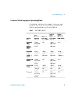
Data and Clock Inputs per Operating Mode
The following table shows the number of data and clock
inputs for each connector on your target system for the
various operating modes of your logic analyzer.
Table 6
16760A logic analyzer
Operating
Mode
E5405A
17-channel
differential
soft touch
E5405A with
half-channel
adapter E5386A
E5402A or
E5406A
34-channel
single-ended
soft touch
E5402A or
E5406A with
half-channel
adapter E5386A
Synchronous
(state)
analysis
200 Mb/s,
400 Mb/s,
800 Mb/s
16 data
plus 1 clock
input (see
note 1)
N/A
32 data
plus 2 clock
inputs
(see note 1)
N/A
Synchronous
(state)
analysis
1250 Mb/s
1500 Mb/s
8 data
plus 1 clock
input (see
note 2)
16 data
plus 1 clock
input
(see note 2)
16 data
plus 1 clock
input
(see note 2)
16 data
plus 1 clock
input
(see note 2)
Eye scan mode
800 Mb/s
16 data
plus 1 clock
input (see
note 1)
N/A
32 data
plus 2 clock
inputs
(see note 1)
N/A
Eye scan mode
1500 Mb/s
8 data
plus 1 clock
input (see
note 2)
16 data
plus 1 clock
input
(see note 2)
16 data
plus 1 clock
input
(see note 2)
16 data
plus 1 clock
input
(see note 2)
Timing mode
16 data
plus 1 clock
input (see
note 3)
N/A
32 data
plus 2 clock
inputs
(see note 3)
N/A


