7-68
Agilent Technologies E5500 Phase Noise Measurement System
Absolute Measurement Examples
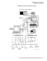
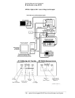
RF Synthesizer using DCFM
Making the
Measurement
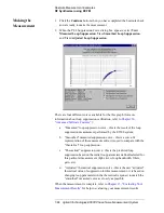
1. Click the Continue button when you have completed the beatnote check
and are ready to make the measurement.
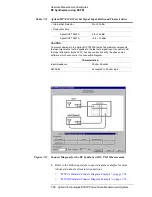
2. When the PLL Suppression Curve dialog box appears, select View
Measured Loop Suppression, View Smoothed Loop Suppression,
and View Adjusted Loop Suppression.
There are four different curves available for the this graph (for more
information about loop suppression verification, refer to
):
a.
“Measured” loop suppression curve - this is the result of the loop
suppression measurement performed by the E5500 system;
b. “Smoothed” measured suppression curve - this is a curve-fit
representation of the measured results, it is used to compare with the
“theoretical” loop suppression;
c.
“Theoretical” suppression curve - this is the predicted loop
suppression based on the initial loop parameters defined/selected for
this particular measurement (kphi, kvco, loop bandwidth, filters,
gain, etc).
d. “Adjusted” theoretical suppression curve - this is the new “adjusted”
theoretical value of suppression for this measurement - it is based on
changing loop parameters (in the theoretical response) to match the
“smoothed” measured curve as closely as possible;
When the measurement is complete, refer to
for help in evaluating your measurement results.


