-ii
Agilent Technologies E5500 Phase Noise Measurement System
guided tour
guidelines
H
hardcopy, 15-7
Agilent/HP 11729C
AM noise, 13-2
option 130, 13-2
Agilent/HP 11848A
Agilent/HP 8662/3A
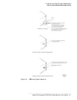
GPIB connectors, removing, A-8
I
Increase in Measured Noise as Ref Source Approaches UUT
Injection locking, 6-16
injection locking bandwidth, 6-17
L
L input port
List of Spurs, 15-16
Low Noise Amplifier (LNA)
Agilent/HP 11848A, 7-81, 7-104, 14-3, 14-7
M
maintenance, preventive, A-1
making the measurement
microwave source, 7-112
RF synthesizer using DCFM, 5-29, 5-52, 7-68, 7-93
making your first measurement, 3-5
markers
Measured, 8-13
measurement
accuracy, 20-2
making your first, 3-5
microwave source, 7-97
noise floor, 6-6
results, 15-1
RF synthesizer using EFC, 7-72
stable RF oscillator, 7-2
your first, 3-1
measurement example
Measurement Noise Floor, 6-6
Measurement Qualifications, 20-2
measurement qualifications, 20-2
measurement results
comparing against expected data, 15-3
obvious problems, 15-2
measurements
Measuring
free-running RF oscillator, 5-30, 7-69, 7-94, 7-113, 13-10, 14-4,
mixers, 8-2, 8-4
MMS modules, removing and replacing, A-11
multipliers, 8-2, 8-4
N
NOISE
Noise Floor
noise floor, 6-6
Noise Floor Limits Due to Peak Tuning Range, 18-12
noise graph, 15-2
Noise Level
noise level, 15-15
noise level of the reference source, 6-7
Noise Plot
stable RF oscillator, 14-4, 14-8
Noise Spec Lines, 5-57, 5-60, 15-10
O
obvious problems
omitting spurs, 5-57
Output, printed, 15-7
outputting the results, 15-7
P
Parameter Summary, 5-57, 5-60, 15-10
parameter summary, 15-12
Peak Tuning Range Required Due to Noise Leve, 18-10
Phase Detector Constant, 5-27, 5-50
phase detector constant, 8-14, 9-12
Phase Detector Sensitivity, 8-10
phase lock loop
Phase Lock Loop Bandwidth vs. Peak Tuning Range, 18-11
Phase Lock Loop Circuit, 6-3
Phase Lock Loop Technique, 6-2, 6-3
phase noise basics, 4-1

