Agilent Technologies E5500 Phase Noise Measurement System
5-53
Expanding Your Measurement Experience
Testing the Agilent/HP 8644B Internal/External 10 MHz
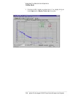
There are four different curves available for the this graph (for more
information about loop suppression verification, refer to
):
a.
“Measured” loop suppression curve - this is the result of the loop
suppression measurement performed by the E5500 system;
b. “Smoothed” measured suppression curve - this is a curve-fit
representation of the measured results, it is used to compare with the
“theoretical” loop suppression;
c.
“Theoretical” suppression curve - this is the predicted loop
suppression based on the initial loop parameters defined/selected for
this particular measurement (kphi, kvco, loop bandwidth, filters,
gain, etc).
d. “Adjusted” theoretical suppression curve - this is the new “adjusted”
theoretical value of suppression for this measurement - it is based on
changing loop parameters (in the theoretical response) to match the
“smoothed” measured curve as closely as possible;
When the measurement is complete, refer to
for help in evaluating your measurement results.
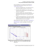
shows a typical phase noise curve for a RF
Synthesizer.
Figure 5-10
Typical Phase Noise Curve for an Agilent/HP 8644B 10 MHz
Measurement.

