Agilent Technologies E5500 Phase Noise Measurement System
7-103
Absolute Measurement Examples
Microwave Source
Beginning the
Measurement
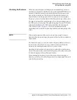
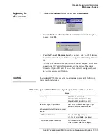
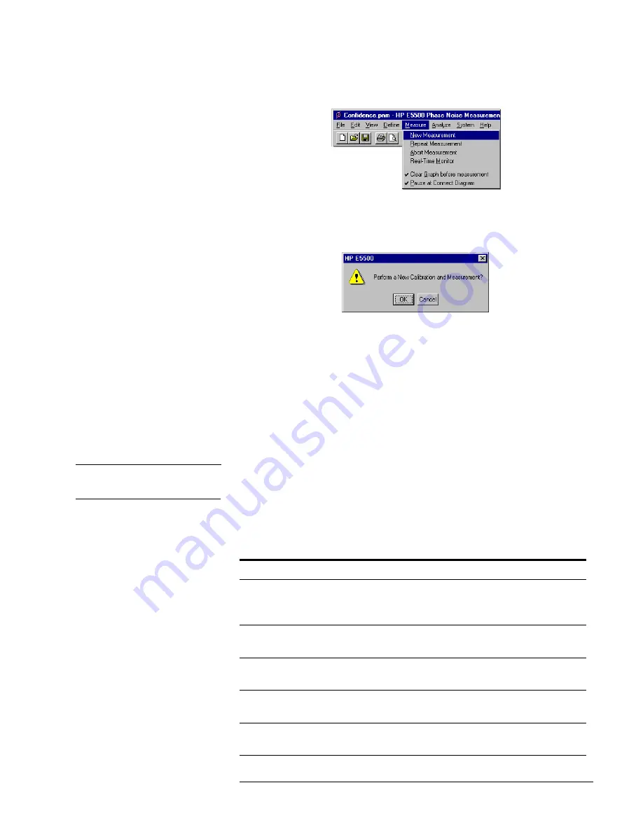
1. From the Measurement menu, choose New Measurement
.
2. When the Perform a New Calibration and Measurement dialog box
appears, click OK.
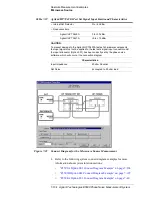
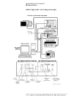
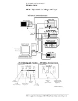
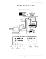
3. When the Connect Diagram dialog box appears, click on the hardware
down arrow and select your hardware configuration from the pull-down
list.
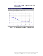
Confirm your connections as shown in the connect diagram. At this time
connect your UUT and reference sources to the test set. The input
attenuator (Option 001 only) has now been correctly configured based
on your measurement definition.
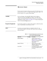
CAUTION
The Agilent/HP 70420A test set’s signal input is subject to the following
limits and characteristics:
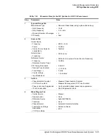
Table 7-19
Agilent/HP 70420A Test Set Signal Input Limits and Characteristics
Limits
Frequency
50 kHz to 1.6 GHz (Std)
50 kHz to 26.5 GHz (Option 001)
50 kHz to 26.5 GHz (Option 201)
Maximum Signal Input Power
Sum of the reference and signal input
power shall not 23 dBm
At Attenuator Output, Operating Level
Range:
• RF Phase Detectors
0 to +23 dBm (Signal Input)
+15 to +23 dBm (Reference Input)
• Microwave Phase Detectors
0 to +5 dBm (Signal Input)
+7 to +10 dBm (Reference Input)


