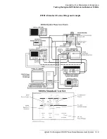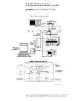
Agilent Technologies E5500 Phase Noise Measurement System
5-27
Expanding Your Measurement Experience
Testing the Agilent/HP 8663A Internal/External 10 MHz
5. The following messages will appear on the display as the system
performs the calibration routines. (You will have time to read through
these message descriptions while the system completes the routines.)
Determining Presence of Beat Note...
An initial check is made to verify that a beatnote is present within the
system’s detection range.
Verifying zero-beat...
The frequency of the beatnote is measured to see if it is within 5% of the
estimated Peak Tuning Range of the system. The system’s Peak Tuning
Range is the portion of the voltage-controlled-oscillator (VCO) source’s
tuning range being used for the measurement.
When the system measures the phase noise of a signal source using the
Phase Lock Loop technique (the technique being used in this example) it
requires that one of the two sources used in the setup is a VCO. As you will
see later in this demonstration, you will be required to estimate the tuning
range of the VCO source you are using when you set up your own Phase
Lock Loop measurements.
Zero beating sources...
The center frequencies of the sources are now adjusted, if necessary, to
position the beatnote within the 5% range. The adjustment is made with the
tune voltage applied to the VCO source set at its nominal or center position.
Measuring the VCO Tuning Constant...
The tuning sensitivity (Hz/V) of the VCO source is now precisely
determined by measuring the beatnote frequency at four tune voltage
settings across the tuning range of the VCO source. Linearity across the
tuning range is also verified
Measuring the Phase Detector Constant...
The transfer characteristics (V/rad) of the test set’s phase detector are now
determined for the specific center frequency and power level of the sources
being measured.
Measuring PLL suppression...
The required correction data is created to compensate for the phase noise
suppression which occurs within the bandwidth of the phase lock loop
created for this measurement.
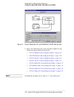
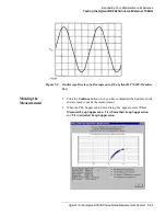
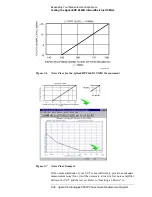
6. The computer displays the PLL suppression curve and associated
measurement values. Press Continue using Adjusted Loop

