background image

72

E5505A Installation Guide

6

Preventive Maintenance

Using, Inspecting, and Cleaning RF Connectors

Taking proper care of cables and connectors will protect your system’s 
ability to make accurate measurements. One of the main sources of 
measurement inaccuracy can be caused by improperly made connections or 
by dirty or damaged connectors.

The condition of system connectors affects measurement accuracy and 
repeatability. Worn, out- of- tolerance, or dirty connectors degrade these 
measurement performance characteristics. 

Repeatability

If you make two identical measurements with your system, the differences 
should be so small that they will not affect the value of the measurement. 
Repeatability (the amount of similarity from one measurement to another 
of the same type) can be affected by:

Dirty or damaged connectors

Connections that have been made without using proper torque 
techniques (this applies primarily when connectors in the system have 
been disconnected, then reconnected).

RF Cable and Connector Care

Connectors are the most critical link in a precision measurement system. 
These devices are manufactured to extremely precise tolerances and must 
be  used  and  maintained  with  care  to protect the measurement accuracy 
and repeatability of your system.

To extend the life of your cables or connectors:

Avoid repeated bending of cables—a single sharp bend can ruin a cable 
instantly.

Avoid repeated connection and disconnection of cable connectors. 

C A U T I O N

Static-Sensitive Devices


This system contains instruments and devices that are static-sensitive. Always take 
proper electrostatic precautions before touching the center conductor of any 
connector, or the center conductor of any cable that is connected to any system 
instrument. Handle instruments and devices only when wearing a grounded wrist or 
foot strap. When handling devices on a work bench, make sure you are working on 
an anti-static worksurface.

Summary of Contents for E5505A

Page 1: ...Agilent Technologies Agilent E5505A Phase Noise Measurement System Installation Guide Fifth Edition December 2009 Create a Recovery DVD Refer to Chapter 5 Recovery ...

Page 2: ...ent prime contract or sub contract Software is delivered and licensed as Commercial computer soft ware as defined in DFAR 252 227 7014 June 1995 or as a commercial item as defined in FAR 2 101 a or as Restricted computer software as defined in FAR 52 227 19 June 1987 or any equivalent agency regulation or contract clause Use duplication or disclosure of Software is subject to Agilent Technologies ...

Page 3: ...stics 14 Table 6 Amplitude ranges 15 15 Power requirements 15 Table 7 E5505A maximum AC power requirements 15 Documentation 17 Figure 2 Navigate to system documentation 17 2 Flat Panel Display Connecting a Rack Mounted Flat Panel Display 20 Table 8 Monitor keyboard and mouse parts listing 20 Figure 3 Display assembly installation 21 3 System Interconnections Making Connections 24 Figure 4 Connect ...

Page 4: ...9 Table 11 Parameter Data for the Agilent N5500A Confidence Test Example 40 Beginning the Measurement 41 Figure 17 Selecting a new measurement 41 Figure 18 Selecting a new measurement 41 Figure 19 50 W connector location for measurement 42 Making the Measurement 42 Figure 20 Typical phase noise curve for a system confidence test 43 Congratulations 43 Additional Assets 44 Configuring an Asset 44 Fi...

Page 5: ... Using the Recovery Partition 61 Re image a New Hard Drive Using the Recovery DVD 62 Partition a New Hard Drive Using Windows Disk Manager 63 Create an Image on the New Recovery Partition 64 System Boot Order Check 65 Hard Drive Recovery Process Kontron PC 66 67 Configuring recovery prompt timing 68 Hard Drive Disk Replacement Procedure 68 Figure 38 Hard Disk Drive Assembly 69 Figure 39 Ejector Le...

Page 6: ...tory Information 86 Safety summary 86 Equipment Installation 86 Environmental conditions 87 Before applying power 87 Ground the instrument or system 88 Fuses and Circuit Breakers 88 Maintenance 89 Safety symbols and instrument markings 89 Table 15 Safety symbols and instrument markings 89 Declaration of Conformity 91 Compliance with German noise requirements 91 Table 16 German noise requirements s...

Page 7: ... and Inspecting the System 9 System Overview 12 System Specifications 14 Documentation 17 This chapter introduces you to the Agilent E5505A Phase Noise Measurement System It contains an overview of the system system specifications and guidelines for unpacking a system It also provides a reading road map for installation documentation ...

Page 8: ...ut you must connect the instruments with the appropriate cables You ll find instrument connection diagrams in Chapter 3 Agilent ships the needed cables with the system Then proceed to Chapter 4 to power on your system and make your first measurement Use Table 1 as a guide to the chapters to use for your model Racked system Benchtop system NOTE If you need to re install the phase noise hardware and...

Page 9: ...am through the holes in the ramp and the base of the crate 4 Remove the remaining crate walls and top as well as the foam padding from the top of the cabinet and the anti static bag covering the cabinet 5 Remove the center restraining bolts and cleats holding the cabinet to the crate base using the socket wrench These bolts are located on the ramp side of the crate and the side opposite 6 Lift the...

Page 10: ...ord Licence Certificate Recovery media kit for Microsoft Windows XP Pro WARNING Do not stand in the path of a system being moved down the incline of the cabinet ramp NOTE Retain all packing material crate pallet boxes foam etc for future use should you need to move the system to another location WARNING Always wear safety glasses or goggles when cutting plastic straps from the shipping container T...

Page 11: ...02A N5507A N5508A N5508A Opt 2 0960 0053 Termination coaxial SMA male 50 Ω 4 3 3 1250 0207 Termination BNC 50 Ω 1 1 1 1250 0780 Adapter Type N male to BNC female 3 2 3 1 1250 0839 Termination coaxial SMC female 50 Ω 1 1 1 1250 1200 Adapter SMA male to BNC female 2 1250 1250 Adapter N male to SMA female 1 2 1 1250 2015 Adapter SMA female to BNC male 1 1250 2076 Termination coaxial SMB female 50 Ω 1...

Page 12: ...tand alone instruments to work in the system This standalone instrument architecture easily configures for various measurement techniques including the PLL reference source technique and delay line and FM discriminator methods The E5505A system is available as a one bay wide System II rack and as a benchtop model Due to the system s flexibility the hardware in the system varies greatly with the op...

Page 13: ...th earlier systems and instruments including the MMS mainframe You may easily integrate existing assets into your E5505A system Table 3 shows the E5505A and earlier model equivalents Figure 1 Agilent E5505A benchtop system typical configuration Table 3 Equivalent system instrument model numbers System or Instrument New Number Old Number Phase noise measurement system E5505A E5501A E5501B E5502B E5...

Page 14: ...102 mm 4 in on all sides System weight Benchtop 1 6 Meter Rack 2 Meter Rack Approximate typical 210 lbs 95 5 kg 431 lbs 195 5 kg 465 lbs 211 kg System dimensions Height Width with rack mounted flat panel display with benchtop PC and display Depth 711 to 915 mm 28 to 36 in 432 mm 17 in n a 1 016 mm 40 in 711 mm 28 in 1 620 mm 64 in 600 mm 23 6 in 1438 mm 56 7 in n a 905 mm 35 7 in 2 020 mm 79 5 in ...

Page 15: ...rrier Frequency Range 50 kHz to 1 6 GHz 1 2 GHz to 26 GHz 50 kHz to 26 5 GHz RF Input R port 0 dBm to 23 dBm 0 dBm to 5 dBm N A RF Input with Option 001 0 dBm to 30 dBm 0 dBm to 30 dBm 0 dBm to 30 dBm Signal Input L port 15 dBm to 23 dBm 7 dBm to 10 dBm Table 5 Operating characteristics continued NOTE Samples of this product have been type tested in accordance with the Agilent Environmental Test M...

Page 16: ...priate for your location For information on an instrument s power line module see the instrument s separate user s guide Downconverter 3 A 2 A Source 6 A 4 A Spectrum analyzer 2 5 A 1 5 A Frequency counter 1 5 A 1 A Oscilloscope 1 A 7 A Table 7 E5505A maximum AC power requirements Component 115 VAC 230 VAC ...

Page 17: ...mation The E5505A system documentation includes Agilent E5505A Phase Noise Measurement System Installation Guide Agilent E5505A Phase Noise Measurement System User s Guide Agilent N5501A N5502A Phase Noise Downconverter Hardware Reference Agilent N5507A Phase Noise Downconverter Hardware Reference Agilent N5500A Phase Noise Test Set Hardware Reference Agilent E5500 Series Phase Noise Measurement S...

Page 18: ...18 E5505A Installation Guide 1 General Information ...

Page 19: ...gilent Technologies 2 Flat Panel Display Connecting a Rack Mounted Flat Panel Display 20 Instructions for mounting a flat panel display and peripheral on a racked system are in this chapter If you re setting up a benchtop system skip to Chapter 3 System Interconnections ...

Page 20: ...e Step Notes 1 Loosely attach the two locking lever bolts and three t bolts to the swing arm assembly Refer to items 1 2 and 3 in Figure 3 on page 21 2 Slide the swing arm assembly into the slide bar from either the top or bottom making sure the t bolts are in the channel tracks Refer to Note 1 in Figure 3 on page 21 3 Tighten the lever bolts to secure the swing arm to the slide bar at the desired...

Page 21: ... to the proper extension cables hanging from the access hole 12 Dress the cables neatly Make sure the cables have enough slack for vertical movement of the swing arm Figure 3 Display assembly installation To attach the swing arm display keyboard and mouse continued Step Notes Agilent SYSTEM POWER RACK FRONT Agilent Technologies LCD Display Slide Bar Swing Arm Sub Assembly Keyboard Mouse Cap 1 4 2 ...

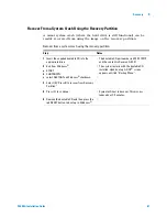
Page 22: ...22 E5505A Installation Guide 2 Flat Panel Display ...

Page 23: ...use the diagrams in this chapter to connect the instruments Otherwise skip to Chapter 4 Measurement Software The instruments in a racked system are already connected CAUTION Agilent Technologies Inc has not provided internet security software for this E5500 phase noise measurement system Connecting the PC to a Local Area Network LAN without first installing internet security software firewall viru...

Page 24: ... with the system either at this time or after running the confidence test 5 Lastly connect the power cord s to the AC power supply CAUTION Make all system hardware connections without AC power applied Failure to do so may result in damage to the hardware GPIB connections are an exception they may be connected with power applied Make connections in a properly grounded environment Agilent recommends...

Page 25: ...01A N5502A N5507A N5508A N5508A Opt 002 0960 0053 Termination coaxial SMA male 50 Ω 4 3 3 1250 0207 Termination BNC 50 Ω 1 1 1 1250 0780 Adapter Type N male to BNC female 3 2 3 1 1250 0839 Termination coaxial SMC female 50 Ω 1 1 1 1250 1200 Adapter SMA male to BNC female 2 1250 1250 Adapter N male to SMA female 1 2 1 1250 2015 Adapter SMA female to BNC male 1 1250 2076 Termination coaxial SMB fema...

Page 26: ...4A 1 meter 1 Test set rear panel GPIB Downconverter rear panel GPIB 8120 3446 GPIB 10834B 2 meter 1 PC rear panel GPIB Test set rear panel GPIB E5505 80001 RF SMA male to BNC male yellow 1 PC digitizer card adapter IN Test set front panel ANALYZER 100 MHz OUT E5505 80002 RF SMA male to BNC male green 1 PC digitizer card adapter OUT Test set rear panel CHIRP SOURCE IN For Test Set Opt 001 E5505 200...

Page 27: ...cense key PC Digitizer card Digitizer input To test set rear panel CHIRP source Digitizer output Optional frequency counter Oscilloscope recommended GPIB GPIB Indicates optional cable NOTE Display 23 dBm 50 kHz 1600MHz MAXIMUM POWER 20 mA MAX TUNE VOLTAGE OUT OF LOCK 100 kHz ANALYZER ANALYZER RF ANALYZER PHASE DET OUTPUT MONITOR 15dBm MIN 50 kHz 1600MHz REF INPUT ERR ACT STATUS SRQ TLK LSN GPIB RM...

Page 28: ...NALYZER RF ANALYZER PHASE DET OUTPUT MONITOR 15dBm MIN 50kHz 1600 MHz 7dBm MIN 1 2 26 5GHz REF INPUT ERR ACT STATUS SRQ TLK LSN GPIB RMT NOISE 0 01Hz 100MHz 1 V Pk 50 50 kHz 26 5GHz INPUT SIGNAL POSSIBLE SIGNAL INPUT 0VDC MAX 100MHz 50 50kHz 1600 MHz 23dBm ATTEN 1 2GHz 26 5GHz 10dBm ATTEN 30dBm MAX WITH ATTENUATOR MAXIMUM POWER 30dBm OUTPUT POWER POWER N5500A Opt 001 Test Set OUTPUT RF ANALYZER 1 ...

Page 29: ...et rear panel CHIRP source Digitizer output Optional frequency counter Oscilloscope recommended GPIB GPIB Indicates optional cable NOTE Display Test set Opt 201 Spectrum analyzer To PC digitizer To reference source optional To oscilloscope or counter monitor optional DC out tune voltage optional E5505a_opt201_conn_dia 14 Apr 04 rev 1 Downconverter Downconverter 50 Ω load Signal input to be downcon...

Page 30: ...30 E5505A Installation Guide 3 System Interconnections ...

Page 31: ...asurement Software 33 Setting GPIB Addresses 53 Specifying Assets for the Confidence Test 36 Running the Software Confidence Test 39 Powering the System Off 56 Chapter 4 contains procedures for powering the system on and off configuring the E5500 software and instruments and conducting a confidence test to verify that all system assets are communicating ...

Page 32: ...cted to a safety power strip turn the strip s power switch to the on position 3 Allow the system to warm up for 30 minutes WARNING Before applying power make sure the AC power input and the location of the system meet the requirements given in Table 4 on page 14 Failure to do so may result in damage to the system or personal injury NOTE Warm up Time The downconverter and RF source instruments cont...

Page 33: ...utdown utility shortcuts from the E5500 folder to your PC desktop You can double click on these icons as an alternative to navigating menus Easy desktop access to the E55000 Shutdown utility is extremely important for restoring functionality when system errors occur Shutdown utility instructions are on page 56 Copy the UI and Shutdown shortcuts to your PC desktop as shown in Figure 9 Figure 8 Log ...

Page 34: ...easurement window appears see Figure 11 on page 35 It shows the phase noise graph CAUTION Always power on the E5505A system before starting the E5500 software Failure to do so produces errors in the stem and may result in inaccurate measurements or an inoperable system In such cases use the E5500 Shutdown icon to launch the Shutdown utility which restores functionality to the system Figure 10 Navi...

Page 35: ...Measurement Software 4 E5505A Installation Guide 35 Figure 11 Main E5500 user interface window E5500_main_screen 23 Mar 04 rev 1 ...

Page 36: ...onnections See Figure 12 2 In the Server Hardware Connections dialog box select the General Assets tab see Figure 13 on page 37 3 Select N5500A 70420A from the Test Set pull down list It may already be selected a A green check mark appears after an automatic I O check has been successfully performed by the software see Figure 13 on page 37 If nothing happens click the Check I O button to manually ...

Page 37: ...sh appears if an I O check is unsuccessful c If the I O check fails click the Asset Manager button to return to the Asset Manager see Figure 14 Figure 13 Successful I O check Figure 14 Failed I O check E5500_server_hardware3 04 Apr 04 rev 1 E5500_server_hardware2 04 Apr 04 rev 1 ...

Page 38: ... Click the Check I O button A green check mark confirms a successful I O check If the I O check is not successful follow the same process as in step 3d to verify instrument configuration and connection 5 From the Swept Analyzer pull down list select E4411A Click the Check I O button A green check mark confirms a successful I O check If the I O check is not successful follow the same process as in ...

Page 39: ...th each other 1 From the File menu choose Open 2 Choose the drive or directory where the file you want is stored 3 In the File Name box open Confidence pnm See Figure 16 The appropriate measurement definition parameters for this example have been pre stored in the Confidence pnm file Table 11 on page 40 lists the parameter data that has been entered for the phase noise test set Confidence Test exa...

Page 40: ...oise input 4 Test Set Tab Input Attenuation LNA Low Pass Filter LNA Gain DC Block PLL Integrator Attenuation Ignore out of lock conditions Pulsed Carrier 0 dB 20 MHz auto checked Auto Gain minimum auto gain 14 dB Not checked 0 dBm Not checked Not checked 5 Graph Tab Title Graph Type X Scale Minimum X Scale Maximum Y Scale Minimum Y Scale Maximum Normalize trace data to a Scale trace data to a new ...

Page 41: ...New Calibration and Measurement prompt appears click YES 3 When the Connect Diagram dialog box appears connect the 50 Ω termination provided with your system to the test set s NOISE IN connector as shown in Figure 19 on page 42 Figure 17 Selecting a new measurement Figure 18 Selecting a new measurement E5500_new_measurement 04 Apr 04 rev 1 E5500_new_cali_meas 04 Apr 04 rev 1 ...

Page 42: ...y Because you selected New Measurement to begin this measurement the System starts by running the routines required to calibrate the current measurement setup Figure 20 shows a typical baseband phase noise plot for an Agilent test set Figure 19 50 Ω connector location for measurement 50 Ω connector ...

Page 43: ...surement of the Agilent phase noise test set s low noise amplifier circuitry provides a convenient way to verify that the system hardware and software are properly configured for making noise measurements Figure 20 Typical phase noise curve for a system confidence test e5500_install_curve_sys_confidence_test rev2 10 10 03 ...

Page 44: ...r hardware connections Configuring an Asset 1 Using Figure 21 as a guide navigate to Asset Manager For this example we invoke the Asset Manager Wizard from the E5500 main screen This is the most common way to add assets NOTE If you have not already connected the assets to the system do so now Be sure to power off the system before making all hardware connections other than GPIB For more informatio...

Page 45: ...he Asset Manager window 3 From the Asset Type pull down list in Choose Asset Role dialog box select Source then click Next Figure 22 Navigate to Add in Asset Manager Figure 23 Select source as asset type E5500_add_source2 16 Apr 04 rev 1 E5500_add_source3 16 Apr 04 rev 1 ...

Page 46: ... Refer to Figure 25 6 In the Address box type 19 7 In the Library pull down list select the Agilent Technologies VISA Click the Next button Figure 24 Choose source E5500_add_source4 16 Apr 04 rev 1 NOTE 19 is the default address for the Agilent 8663A sources including Agilent 8662A 8663A and 8644B Table 12 on page 53 shows the default GPIB address for all system instruments ...

Page 47: ...the Set Model Serial Numbers dialog box type in your source name and its corresponding serial number Click the Next button Figure 25 Select I O library Figure 26 Enter asset and serial number E5500_add_source5 16 Apr 04 rev 1 E5500_add_source6 16 Apr 04 rev 1 ...

Page 48: ...ates itself with the asset you have just configured Click Finish 10 In the Asset Manager window select the source in the left window pane Click the check mark button on the toolbar to verify connectivity Figure 27 Enter comment Figure 28 Click Check button E5500_add_source7 16 Apr 04 rev 1 E5500_add_source8 16 Apr 04 rev 1 ...

Page 49: ...nection to your asset This indicates that you have successfully used the Asset Manager to configure a source 11 To exit the Asset Manager on the menu select Server Exit 12 Perform the procedure Verifying Server Hardware Connections on page 50 Figure 29 Confirmation message E5500_add_source9 16 Apr 04 rev 1 ...

Page 50: ...g Server Hardware Connections 1 From the System menu choose Server Hardware Connections 2 Select the Sources tab Figure 30 Navigate to server hardware connections Figure 31 Select Sources tab E5500_add_source10 16 Apr 04 rev 1 E5500_add_source11 16 Apr 04 rev 1 ...

Page 51: ...erformed by the software If nothing happens click the Check I O button to manually initiate the check b A red circle with a slash appears if the I O check is unsuccessful c If the I O check fails click the Asset Manager button to return to the Asset Manager see Figure 33 Figure 32 Successful I O check Figure 33 Failed I O check E5500_add_source12 16 Apr 04 rev 1 E5500_add_source13 16 Apr 04 rev 1 ...

Page 52: ...ured correctly Do the following Check your system hardware connections Click the green check mark button on the Asset Manager s toolbar to verify connectivity Return to Server Hardware Connections and click the Check I O button to re check it NOTE Use the same process to add additional assets to your E5505A system ...

Page 53: ...e the Asset Manager as shown in the easy procedure starting on page 54 Table 12 Default GPIB addresses Instrument Address Test set 20 Downconverter 28 Microwave downconverter 28 RF analyzer 17 FFT analyzer PC digitizer card 1 FFT analyzer 89410A 18 Source 1 19 Source 2 23 Counter 3 Agilent E1430 VXI digitizer 129 Agilent E1437 VXI digitizer 192 Agilent E1420B VXI counter 48 Agilent E1441 VXI ARB 8...

Page 54: ...ss 1 On the E5500 main menu select System Asset Manager 2 Double Click on the desired instrument in the Asset Manager list left pane Figure 34 Asset Manager on System menu Figure 35 Asset Manager window E5500_asset_manager 23 Mar 04 rev 1 E5500_asset_mgr_screen 23 Mar 04 rev 1 ...

Page 55: ...are 4 E5505A Installation Guide 55 Type the desired address in the dialog box 3 Click OK 4 To exit the Asset Manager on the menu select Server Exit Figure 36 GPIB address dialog box E5500_edit_asset_info 04 Apr 04 rev 1 ...

Page 56: ...functionality to the system If you still receive errors after running the E5500 Shutdown utility call your local Agilent Technologies Service Center To run the E5500 Shutdown utility 1 Double Click on the E5500 Shutdown utility shortcut on the PC desktop and follow the onscreen instructions You can also navigate to it using the menu path Start Agilent Subsystems E5500 Phase Noise Shutdown 2 When t...

Page 57: ...e Using Windows Disk Manager 63 Create an Image on the New Recovery Partition 64 Hard Drive Recovery Process Kontron PC 66 Chapter 5 contains recovery procedures for both the Advantech PC and Kontron PC NOTE It is Important to create a backup recovery DVD The recovery DVD is the only way to reinstall the original Windows XP operating system after replacing the hard drive For information about crea...

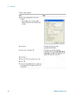
Page 58: ... DVD Step Notes 1 Turn the computer ON Follow the on screen instruction to accept the Windows licensing agreement 2 Insert the provided DVD R into the DVD burner drive A message appears Blank CD DVD inserted A dialog box appears Formatting 3 Click NO for formatting 4 Launch Windows Explorer 5 Expand Explorer to view Recovery D This is the recovery partition You see a folder named System Volume Inf...

Page 59: ...ens 12 Drag files CDR00001 GHO and CDR00001 GHS to the right pane of the Burn Now window Use the control key Ctrl to select both files These two files total about 4 GBytes of content 13 Close the Explorer window by selecting the X in the upper right corner of the window 14 In the ULead Burn Now Data Disc window select the Burn icon 5th from left Single click the icon A small Burn Disc window appea...

Page 60: ...akes approximately 20 minutes 17 Select Exit then Click OK Operation successfully completed The written DVD is ejected Keep this DVD in a safe place The DVD will be required if you replace the hard drive on your PC 18 Click Next 19 Select the Disc menu then select Exit 20 Click OK 21 Close the Digital Media Center window by selecting the X in the upper right corner of the window Create a recovery ...

Page 61: ... bootable CD into the appropriate drive The bootable CD part number is E5500 10010 and the content is Revision A 00 01 2 Exit from Windows a START b SHUTDOWN c select RESTART on Windows shutdown The system restarts with the bootable CD installed Upon boot up A DOS screen appears entitled Backup Menu 3 Select B Press B to recover from Recovery Partition 4 Press C to continue Symantec Ghost takes ov...

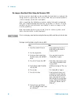
Page 62: ... system boot order Reimage a new hard drive using the recovery DVD Step Notes 1 Have the bootable CD in hand The bootable CD part number is E5500 10010 and the content is Revision A 00 01 2 Turn the computer ON 3 Quickly put the bootable CD into the drive and press the red RESET button The system boots up and the Backup Menu appears 4 Press C to Recover from DVD The backup screen prompts you to Pl...

Page 63: ...artition Wizard screen appears 5 Click Next Select partition type appears 6 Highlight Primary Partition This is the default 7 Click Next The Specify Partition Size screen appears 8 To Specify partition size use the default Set partition size maximum disk space in Mbytes This is the default 9 Click Next 10 Select Assign the following drive letter Use the default D 11 Click Next The Format Partition...

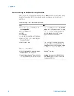
Page 64: ...ESTART on Windows shutdown The system restarts with the bootable CD installed Upon boot up A DOS screen appears entitled Backup Menu 3 Press A Press A to create an image on Recovery Partition 4 Press C to continue Symantec Ghost now takes over to create an image on the recovery partition from the primary partition This image includes hidden files This process takes about 4 5 minutes 5 Remove the b...

Page 65: ...ars 3 Press the Enter button 4 Use the down arrow button to highlight First Boot Device 5 Press the Enter button 6 Use the down arrow button to select CDROM Selects the CDROM as the 7 Press the Enter button 8 Use the down arrow button to highlight Second Boot Device 9 Press the Enter button 10 Use the down arrow button to select FLOPPY 11 Press the Enter button 12 Verify that the Third Boot Device...

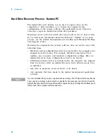
Page 66: ...ms Windows system configurations that were made after the computer was shipped from the factory For example Windows and Service Pack updates user accounts and windows configuration settings After an Agilent Recovery these configurations need to be redone Additional software that was installed after the computer was shipped from the factory After an Agilent Recovery that software needs to be re ins...

Page 67: ...structions to recover the image of the C drive Press 2 then press Enter to select the recovery Press 1 then press Enter to continue Press 1 then Enter to confirm It may take up to 25 minutes for this process to complete After exiting the Agilent Recovery System the computer reboots NOTE Additional recovery steps may be required to fully recover the system to a more current working state This could...

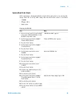
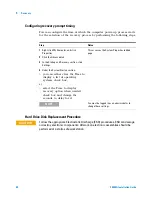
Page 68: ... Click the Advanced tab 3 In the Startup and Recovery section click Settings 4 Under the System Startup section you can either clear the Time to display a list of operating systems check box or select the Time to display recovery option when needed check box and change the seconds to delay for it NOTE You must be logged in as an administrator to change these settings CAUTION Follow the appropriate...

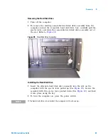
Page 69: ...d disk drive assembly out of the slot Refer to Figure 38 Figure 38 Hard Disk Drive Assembly Installing the Hard Disk Drive 1 Insert the alternate hard disk drive assembly into the slot on the computer with the ejector lever pulled up See Figure 39 Secure the assembly with the ejector lever pushed down See Figure 40 and lock it into place using the key 2 To turn the computer on press the power swit...

Page 70: ...70 E5505A Installation Guide 5 Recovery Figure 39 Ejector Lever Pulled Up Figure 40 Ejector Lever Pushed Down ...

Page 71: ...71 Agilent E5505A Phase Noise Measurement System Installation Guide Agilent Technologies 6 Preventive Maintenance Using Inspecting and Cleaning RF Connectors 72 General Procedures and Techniques 76 ...

Page 72: ...t using proper torque techniques this applies primarily when connectors in the system have been disconnected then reconnected RF Cable and Connector Care Connectors are the most critical link in a precision measurement system These devices are manufactured to extremely precise tolerances and must be used and maintained with care to protect the measurement accuracy and repeatability of your system ...

Page 73: ...o the proper value Proper Connector Torque Provides more accurate measurements Keeps moisture out of the connectors Eliminates radio frequency interference RFI from affecting your measurements The torque required depends on the type of connector Refer to Table 13 Do not overtighten the connector Never exceed the recommended torque when attaching cables Connector Wear and Damage Look for metal part...

Page 74: ...ed States Environmental Protection Agency and contains tetrafluoroethane You can order this aerosol from Agilent see Table 14 2 Use alcohol and a lint free cloth to wipe connector surfaces Wet a small swab with a small quantity of alcohol and clean the connector with the swab 3 Allow the alcohol to evaporate off of the connector before making connections CAUTION Do not allow excessive alcohol to r...

Page 75: ...ld only be performed with the instruments mains power cord disconnected in a well ventilated area Connector cleaning should be accomplished with the minimum amount of alcohol Prior to connector reuse be sure that all alcohol used has dried and that the area is free of fumes WARNING If flammable cleaning materials are used the material should not be stored or left open in the area of the equipment ...

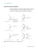
Page 76: ...he various cable and connector types used in the system Read this section before attempting to remove or install an instrument Each connector type may have unique considerations Always use care when working with system cables and instruments Figure 41 GPIB 3 5 mm Type N power sensor and BNC connectors GPIB Type Connector ...

Page 77: ... the connector nut counter clockwise with a 5 16 inch wrench Always reconnect using an 8 inch lb torque wrench Agilent part number 8720 1765 Semirigid cables are metal tubes custom formed for this system from semirigid coax cable stock 3 5 mm Connectors with a gold hex nut The semirigid cables that go to the RF outputs of some devices have a gold connector nut These do not turn Instead the RF conn...

Page 78: ...ning them Turn the silver nut clockwise by hand until it is snug then tighten with an 8 inch lb torque wrench part number 8720 1765 Bent Semirigid Cables Semirigid cables are not intended to be bent outside of the factory An accidental bend that is slight or gradual may be straightened carefully by hand Semirigid cables that are crimped will affect system performance and must be replaced Do not at...

Page 79: ...isconnect all cables on the front and on the rear panel Most cables are fairly easy to remove and reconnect and have no special considerations besides making sure you put the cables back in the right place Semirigid cables require more care especially when reconnecting them Make sure all semirigid cables on the front and back of an instrument are fully disconnected before removing the unit 3 When ...

Page 80: ...truments Note the location of cables for re installation 5 Remove the four corner screws on the front of the rack panel that secures the instruments in place The screws are located near the corners of the face of the instrument Use a 2 Phillips screwdriver 6 Slide both instruments as a single unit out from the front of the rack and set them on a secure flat surface 7 Detach the lock links that sec...

Page 81: ... links Rear links To remove an instrument from a benchtop system 1 Power off each instrument in the system For details see Powering the System Off on page 56 2 Unplug the selected instrument s power cord from the AC power supply 3 Remove the power cord and other cables from the front and rear of the instrument Note the location of cables for re installation ...

Page 82: ...cial considerations besides making sure you put the cables back in the right place Semirigid cables require more care especially when reconnecting them Make sure all semirigid cables on the front and back of an instrument are fully disconnected before removing the unit 3 To reconnect the semirigid cables carefully align them before you insert the male connector Do not insert the male pin in at an ...

Page 83: ...ack mount ears The rack mount ears stop the instruments at the correct depth 5 Replace the rack panel in front of the instruments and secure the four corner screws The screws are located near the corners of the face of the instrument Use a 2 Phillips screwdriver 6 Confirm that the instrument is turned off 7 Connect the appropriate cables to the instruments front and rear including the power cords ...

Page 84: ...84 E5505A Installation Guide 6 Preventive Maintenance ...

Page 85: ...rmation which you should review prior to working with your Agilent system The information contained in it applies to all Agilent supplied instruments in the system and the system as a whole It also contains information on servicing and obtaining support for an Agilent system or instrument including procedures for removing an instrument from a system returning it to Agilent and re installing it ...

Page 86: ... this product are Class 1 LEDs per IEC 60825 1 Equipment Installation Install the instrument or system so that the detachable power cord is readily identifiable and is easily reached by the operator The detachable power cord is the disconnecting device It disconnects the mains circuits from the mains supply before other parts of the instrument or system The instrument front panel switch is only a ...

Page 87: ... CAUTION Unless otherwise noted in the specifications this instrument or system is intended for indoor use in an installation category II pollution degree 2 environment CAUTION Ventilation Requirements When installing the product in a cabinet the convection into and out of the product must not be restricted The ambient temperature outside the cabinet must be less than the maximum operating tempera...

Page 88: ...ption of the protective conductor inside or outside of the products is likely to make the product dangerous Intentional interruption is prohibited IEC 348 clauses 17 3 3 c and 17 3 4 CAUTION Always use the three prong AC power cord supplied with this product Failure to ensure adequate earth grounding by not using this cord may cause product damage CAUTION The detachable power cord is the disconnec...

Page 89: ...nformation about conditions and comply with international regulations Table 15 defines the symbols and markings you may find in a manual or on an instrument WARNING To prevent electrical shock disconnect the instrument and or system from mains before cleaning Use a dry cloth or one slightly dampened with water to clean the external case parts Do not attempt to clean internally Table 15 Safety symb...

Page 90: ... connecting it with the mains supply Instrument markings Definition The CE mark is a registered trademark of the European Community This symbol indicates compliance with the China RoHS regulations for paper fiberboard packaging China RoHS regulations include requirements related to packaging and require compliance to China standard GB 18455 2001 This symbol indicates separate collection for electr...

Page 91: ...enlaermrerordnung 3 GSGV Deutschland Compliance with Canadian EMC requirements This ISM device complies with Canadian ICES 001 Cet appareil ISM est conforme a la norme NMB du Canada 1SM1 A This text indicates that the instrument is an Industrial Scientific and Medical Group 1 Class A product CISPER 11 Clause 4 ICES NMB 001 This text indicates product compliance with the Canadian Interference Causi...

Page 92: ...field engineer WARNING There are no user serviceable parts inside the system Any servicing instructions are for use by qualified personnel only To avoid electrical shock do not perform any servicing unless you are qualified to do so WARNING The opening of covers or removal of parts is likely to expose dangerous voltages Disconnect the product from all voltage sources while it is being opened NOTE ...

Page 93: ...nd any error message Ship the analyzer using the original or comparable antistatic packaging materials Contact Agilent for instructions on where to ship your analyzer NOTE Agilent Technologies reserves the right to reformat or replace the internal hard disk drive in your analyzer as part of its repair This will erase all user information stored on the hard disk It is imperative therefore that you ...

Page 94: ...Figure 43 The serial number has two parts The first part makes up the prefix and consists of four digits and a letter The second part makes up the suffix and consists of the last five digits on the label The serial number prefix is the same for all identical instruments it changes only if the electrical or physical functionality differs between instruments However the serial number suffix changes ...

Page 95: ...nal shipping container or a strong shipping container that is made of double walled corrugated cardboard with 159 kg 350 lb bursting strength The shipping container must be large and strong enough to accommodate your instrument and allow at least 3 to 4 inches on all sides for packing material 4 Seal the shipping container securely with strong nylon adhesive tape 5 Mark the shipping container FRAG...

Page 96: ...96 E5505A Installation Guide A Service Support and Safety Information ...

Reviews: