background image

Agilent Part Number: E8356-90052

Printed in USA

November 2001

Installation Note

Extended Frequency Range Upgrade Kits

For PNA Series RF Network Analyzers (E8356A and E8357A)

Network Analyzer
Model Number

Upgrade Kit
Part Number

Frequency
Extension

E8356A

E8356-60104

3 GHz to 6 GHz

E8356A

E8356-60105

3 GHz to 9 GHz

E8357A

E8357-60101

6 GHz to 9 GHz

Summary of Contents for E8356-60104

Page 1: ...n Note Extended Frequency Range Upgrade Kits For PNA Series RF Network Analyzers E8356A and E8357A Network Analyzer Model Number Upgrade Kit Part Number Frequency Extension E8356A E8356 60104 3 GHz to 6 GHz E8356A E8356 60105 3 GHz to 9 GHz E8357A E8357 60101 6 GHz to 9 GHz ...

Page 2: ...o this material including but not limited to the implied warranties of merchantability and fitness for a particular purpose Agilent shall not be liable for errors contained herein or for incidental or consequential damages in connection with the furnishing performance or use of this material Copyright 2001 Agilent Technologies Inc All rights reserved ...

Page 3: ...gilent on page 5 Description of the Upgrades These upgrade kits are used to extend the frequency range of the E8356A PNA RF network analyzer from 3 GHz to either 6 GHz or 9 GHz E8357A PNA RF network analyzer from 6 GHz to 9 GHz Products affected E8356A and E8357A all options See NOTE below Installation to be performed by Agilent service center personnel qualified by Agilent or customer Estimated i...

Page 4: ...Qty Part Number Installation note this document 1 E8356 90052 License key certificate 1 5964 5136 Model number nameplate 1 E8357 80001 A12 source assembly 1 E8356 60012 Table 2 Option 009 Upgrade Kit to Extend the E8356A to 9 GHz E8356 60105 Description Qty Part Number Installation note this document 1 E8356 90052 License key certificate 1 5964 5136 Model number nameplate 1 E8358 80001 A12 source ...

Page 5: ...47 New Zealand tel 0 800 738 378 fax 64 4 495 8950 Japan tel 81 426 56 7832 fax 81 426 56 7840 Singapore tel 1 800 375 8100 fax 65 836 0252 Malaysia tel 1 800 828 848 fax 1 800 801 664 India tel 1 600 11 2929 fax 000 800 650 1101 Hong Kong tel 800 930 871 fax 852 2506 9233 Taiwan tel 0800 047 866 fax 886 2 25456723 Philippines tel 632 8426802 tel PLDT subscriber only 1 800 16510170 fax 632 8426809...

Page 6: ...hin the network analyzer Static electricity can build up on your body and can easily damage sensitive internal circuit elements when discharged Static discharges too small to be felt can cause permanent damage To prevent damage to the instrument always wear a grounded wrist strap having a 1 MΩ resistor in series with it when handling components and assemblies always use a grounded conductive table...

Page 7: ... option number on the certificate is either 1F6 for a 6 GHz upgrade or 1F9 for a 9 GHz upgrade If either the serial number or the option number does not match the expected results you will not be able to install the option If this is the case contact Agilent for assistance Refer to Getting Assistance from Agilent on page 5 Description Model Part Number Tools for A12 Source Assembly Replacement E83...

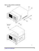
Page 8: ...es in the vertical position Do not place the analyzer on its front panel without the handles This will damage the front panel assemblies 1 Disconnect the power cord if it has not already been disconnected 2 With a T 20 TORX driver remove the strap handles item by loosening the screws item on both ends until the handle is free of the analyzer 3 With a T 20 TORX driver remove the four rear panel fee...

Page 9: ...Installation Note E8356 90052 9 Figure 2 Outer and Inner Cover Removal ...

Page 10: ...o note their locations for reconnection later CAUTION Be careful not to damage the center pins of the semirigid cables Some flexing of the cables is necessary to remove the assembly Do not over bend the semirigid cables 3 With a 5 16 in torque wrench disconnect the semirigid cable item from the bottom of the A12 source assembly CAUTION To avoid damage to the semirigid cable item pull down on the c...

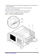
Page 11: ...om of the A12 source assembly 7 Reconnect the three flexible cables item to the A12 source assembly Refer to Figure 3 for the following steps 8 Reinstall the A31 hard disk drive assembly into its original position 9 With a T 10 TORX driver replace the mounting screw item Figure 4 A12 Source Assembly Replacement ...

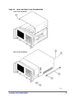
Page 12: ...tall the Outer Cover CAUTION This procedure is best performed with the analyzer resting on its front handles in the vertical position Do not place the analyzer on its front panel without the handles This will damage the front panel assemblies 1 Slide the cover onto the frame 2 With a T 20 TORX driver install the four rear panel feet item by installing the center screws item 3 Slide the four bottom...

Page 13: ...Installation Note E8356 90052 13 Figure 5 Inner and Outer Cover Reinstallation ...

Page 14: ...ect click NO and repeat the repair 8 When the installation is complete click Exit Front Panel Keys Procedure 1 In the COMMAND block press Menu Dialog 2 In the NAVIGATION block press the right tab and arrow keys to move over to the System menu and down to the Service selection Press the right tab to display the extended menu and the arrows to select Option Enable Press Click 3 Press Menu Dialog the...

Page 15: ...fy that the new model number is shown correctly in the display Click OK 3 On the analyzer front panel press Preset Verify that the full frequency range of the analyzer is correct Front Panel Keys Procedure 1 In the COMMAND block press Menu Dialog 2 In the NAVIGATION block press the right tab and arrow keys to move over to the Help menu and down to the About Network Analyzer selection Press Click 3...

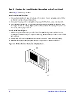
Page 16: ...nt panel surface it can be removed by rubbing it with your finger Do not use a sharp object to remove this adhesive If necessary the surface can be cleaned with isopropol alcohol Install the New Nameplate 1 Remove the protective backing from the new nameplate to expose the adhesive Avoid touching the adhesive with your fingers as this may affect its ability to adhere to the front panel surface 2 L...

Page 17: ...urce power across its full frequency range The differences between Port 1 and Port 2 are negligible therefore a Port 2 adjustment is not required 1 Connect the equipment as shown in Figure 7 Connect a GPIB cable between the network analyzer and the power meter Figure 7 Setup for the Source Calibration Adjustment 2 On the System menu point to Service Adjustments then click Source Calibration 3 Ensu...

Page 18: ...just the B receiver at Port 2 The adjustment is repeated using a signal from Port 2 to adjust the A receiver at Port 1 1 Connect the equipment as shown in Figure 8 Connect a GPIB cable between the network analyzer and the power meter Figure 8 Setup for the Receiver Calibration Adjustment Figure 9 Setup for the Receiver Calibration Adjustment of Port 2 2 On the System menu point to Service Adjustme...

Page 19: ...ge 5 Although the analyzer functions its performance relative to its specifications has not been verified for the additional frequency range enabled by this upgrade It is recommended that a full instrument calibration be performed using the N2721A performance test software If the testing of the analyzer s full range of specifications is not required a system verification can be performed Refer to ...

Reviews: