background image

User’s Guide

7

     E8362/3/4C Option H85

Specifications: Front Panel Jumpers and Test Ports

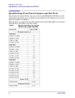
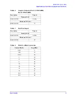
Table 4

Source Outputs (Port 1 SOURCE OUT 
and Port 2 SOURCE OUT)

Description Typical 

(dBm)

Maximum Output Level

E8362CH85

45 MHz to 500 MHz

4

500 MHz to 2 GHz

5

2 GHz to 10 GHz

5

10 GHz to 20 GHz     

2

E8363CH85

45 MHz to 500 MHz

3.5

500 MHz to 2 GHz

5

2 GHz to 10 GHz

5

10 GHz to 20 GHz     

3.5

20 GHz to 30 GHz 

0

30 GHz to 40 GHz 

–2.5

E8364CH85

45 MHz to 500 MHz

3.5

500 MHz to 2 GHz

5

2 GHz to 10 GHz

5

10 GHz to 20 GHz     

3.5

20 GHz to 30 GHz 

0

30 GHz to 40 GHz 

–2.5

40 GHz to 45 GHz 

–.5

45 GHz to 50 GHz 

10

Damage Level

E8362/3/4CH85

30 dBm

Maximum DC Level

E8362/3/4CH85

0 V

Summary of Contents for E8362

Page 1: ...NA Series High Power Configurable Test Set Manufacturing Part Number E8364 90040 Printed in USA May 2008 Supersede March 2008 Copyright 2008 Agilent Technologies Inc All rights reserved Advanced Test Equipment Rentals www atecorp com 800 404 ATEC 2832 Established 1981 ...

Page 2: ... DOCUMENT THAT CONFLICT WITH THESE TERMS THE WARRANTY TERMS IN THE SEPARATE AGREEMENT WILL CONTROL DFARS Restricted Rights Notice If software is for use in the performance of a U S Government prime contract or subcontract Software is delivered and licensed as Commercial computer software as defined in DFAR 252 227 7014 June 1995 or as a commercial item as defined in FAR 2 101 a or as Restricted co...

Page 3: ...e fully understood and met Definitions Specifications describe the performance of parameters covered by the product warranty temperature 0 to 55 C unless otherwise noted Typical describes additional product performance information that is not covered by the product warranty It is performance beyond specification that 80 of the units exhibit with a 95 confidence level over the temperature range 20 ...

Page 4: ...iv User sGuide ...

Page 5: ...Switch Setup 26 Final Setup 27 Service Information 30 Replaceable Parts 30 Safety and Regulatory Information 31 Introduction 31 Cleaning the Instrument 31 Connector Care and Cleaning 31 Declaration of Conformity 31 Statement of Compliance 31 General Safety Considerations 32 Safety Earth Ground 32 Before Applying Power 32 Servicing 33 Regulatory Information 34 Instrument Markings 34 Compliance with...

Page 6: ...Contents 2 User sGuide ...

Page 7: ...User s Guide 1 E8362 3 4C Option H85 ...

Page 8: ...igh power measurements The user must supply there own amplifier s and external components such as high power couplers attenuators and isolators to configure the analyzer for high power These components are not supplied or included with the Option H85 The user is responsible to ensure that these components meet their DUT requirements and also protect the PNA from damage Therefore it is very importa...

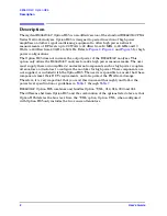
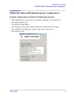
Page 9: ...n Default Configuration Includes the Following Options UNL Extended power range bias tee Adds two attenuators and two bias tee 014 Configurable test set 080 Frequency Offset Mode 081 Reference switch Add an internal solid state switch in the R1 reference 016 35 dB Receiver Attenuators Add two step receiver attenuators H85 Delete bias tee ...

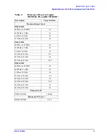
Page 10: ...ested at the factory in the field or at service centers Table 1 Measurement Receiver Inputs RCVR A IN and RCVR B IN Description Typical dBm Maximum Input Level E8362CH85 45 MHz to 500 MHz 15 500 MHz to 2 GHz 11 2 GHz to 10 GHz 11 10 GHz to 20 GHz 11 E8363CH85 45 MHz to 500 MHz 14 500 MHz to 2 GHz 10 2 GHz to 10 GHz 10 10 GHz to 20 GHz 10 20 GHz to 30 GHz 14 5 30 GHz to 40 GHz 16 5 E8364CH85 45 MHz...

Page 11: ...Hz to 2 GHz 11 2 GHz to 10 GHz 11 10 GHz to 20 GHz 11 E8363CH85 45 MHz to 500 MHz 14 500 MHz to 2 GHz 10 2 GHz to 10 GHz 10 10 GHz to 20 GHz 9 5 20 GHz to 30 GHz 14 30 GHz to 40 GHz 15 5 E8364CH85 45 MHz to 500 MHz 14 500 MHz to 2 GHz 10 2 GHz to 10 GHz 10 10 GHz to 20 GHz 9 5 20 GHz to 30 GHz 14 30 GHz to 40 GHz 15 5 40 GHz to 45 GHz 14 45 GHz to 50 GHz 15 Damage Level E8362 3 4CH85 15 dBm Maximu...

Page 12: ...4 500 MHz to 2 GHz 23 2 GHz to 10 GHz 23 10 GHz to 20 GHz 26 E8363CH85 45 MHz to 500 MHz 11 5 500 MHz to 2 GHz 10 5 2 GHz to 10 GHz 11 10 GHz to 20 GHz 11 20 GHz to 30 GHz 11 30 GHz to 40 GHz 11 E8364CH85 45 MHz to 500 MHz 11 5 500 MHz to 2 GHz 10 5 2 GHz to 10 GHz 11 10 GHz to 20 GHz 11 20 GHz to 30 GHz 11 30 GHz to 40 GHz 11 40 GHz to 45 GHz 11 45 GHz to 50 GHz 15 Damage Level E8362 3 4CH85 20 d...

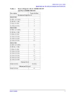
Page 13: ...4 500 MHz to 2 GHz 5 2 GHz to 10 GHz 5 10 GHz to 20 GHz 2 E8363CH85 45 MHz to 500 MHz 3 5 500 MHz to 2 GHz 5 2 GHz to 10 GHz 5 10 GHz to 20 GHz 3 5 20 GHz to 30 GHz 0 30 GHz to 40 GHz 2 5 E8364CH85 45 MHz to 500 MHz 3 5 500 MHz to 2 GHz 5 2 GHz to 10 GHz 5 10 GHz to 20 GHz 3 5 20 GHz to 30 GHz 0 30 GHz to 40 GHz 2 5 40 GHz to 45 GHz 5 45 GHz to 50 GHz 10 Damage Level E8362 3 4CH85 30 dBm Maximum D...

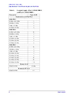
Page 14: ...MHz 1 500 MHz to 2 GHz 2 2 GHz to 10 GHz 2 10 GHz to 20 GHz 2 E8363CH85 45 MHz to 500 MHz 0 5 500 MHz to 2 GHz 1 2 GHz to 10 GHz 2 10 GHz to 20 GHz 3 20 GHz to 30 GHz 4 30 GHz to 40 GHz 5 E8364CH85 45 MHz to 500 MHz 0 5 500 MHz to 2 GHz 1 2 GHz to 10 GHz 2 10 GHz to 20 GHz 3 20 GHz to 30 GHz 4 30 GHz to 40 GHz 5 5 40 GHz to 45 GHz 5 5 45 GHz to 50 GHz 10 Damage Level E8362 3 4CH85 30 dBm Maximum D...

Page 15: ...R ARM Description Typical Damage Level E8362 3 4CH85 30 dBm Maximum DC Level E8362 3 4CH85 7 V Table 7 Test Port Input Description Typical Damage Level E8362 3 4CH85 30 dBm Maximum DC Level E8362 3 4CH85 0 V Table 8 Watts to dBm Conversion Linear Watts Log dBm 0 001 0 0 01 10 0 100 20 1 30 2 33 4 36 10 40 20 43 40 46 50 47 100 50 200 53 ...

Page 16: ...5 2 to 16 0 1 0 045 to 0 748 15 16 0 to 20 0 2 0 748 to 1 5 E8362 3CH85 3 1 5 to 3 0 16 20 0 to 22 8 4 3 0 to 3 8 17 22 8 to 25 6 5 4 0 to 4 5 18 25 6 to 30 6 4 5 to 4 8 19 30 0 to 32 0 7 4 8 to 6 0 20 32 0 to 36 0 8 6 0 to 6 4 21 36 0 to 38 4 9 6 4 to 7 6 22 38 4 to 40 10 7 6 to 10 0 E8364CH85 11 10 0 to 12 0 23 40 0 to 45 6 12 12 0 to 12 8 24 45 6 to 48 0 13 12 8 to 15 2 25 48 0 to 50 0 ...

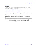
Page 17: ...iagrams for external component connections and or operating constraints when utilizing the high power capability of the Agilent E8362 3 4C Option H85 When using the Agilent E8362 3 4C Option H85 in the high power configuration the analyzers R1 Input path must be set to External flow through R1 front panel jumper loop NOTE The internal firmware of the PNA has not been modified for this option The P...

Page 18: ...12 User s Guide E8362 3 4C Option H85 Operation Figure 1 E8362 3 4C Option H85 2 Port Block Diagram Figure 2 Front Panel Display ...

Page 19: ...coupler isolator and attenuators The isolator reference and measured receiver attenuators are optional They are dependent on the high power couplers coupling factor amplifiers reverse isolation and power required to test the device The attenuator located at the high power coupler arm may not be required if the coupling factor attenuates the signal adequately for the reference receiver channel The ...

Page 20: ...Port Two Way High Power Configuration Booster Amplifier RF INPUT RF OUTPUT Coupler Arm 20 dB Coupler Main Coupler Output Fix Attenuator CPLR ARM RCVR A IN SOURCE OUT RCVR R1 IN CPLR THRU CPLR ARM RCVR B IN Booster Amplifier RF INPUT RF OUTPUT Coupler Arm 20 dB Coupler Main Coupler Output Fix Attenuator SOURCE OUT RCVR R2 IN CPLR THRU ...

Page 21: ...iguration Fix Attenuator Fix Attenuator 2 Port One Way High Power Configuration Booster Amplifier RF INPUT RF OUTPUT Coupler Arm 20 dB Coupler Main Coupler Output Fix Attenuator CPLR ARM RCVR A IN SOURCE OUT RCVR R1 IN CPLR THRU CPLR ARM RCVR B IN Isolator In Out SOURCE OUT CPLR THRU DUT ...

Page 22: ...16 User s Guide E8362 3 4C Option H85 Operation Figure 5 2 Port Forward DUT Configuration Fix Attenuator DUT 2 Port Forward DUT Configuration CPLR ARM RCVR B IN SOURCE OUT CPLR THRU Isolator In Out ...

Page 23: ... You may choose to optimize your measurement performance by using Table 1 through Table 7 on Page 4 through Page 9 For all high power configurations refer to the specifications listed in Table 1 through Table 8 CAUTION Prior to powering up the booster amplifier it is highly recommended that the user verify the RF power levels seen by the various elements of the test setup At high power levels an i...

Page 24: ...f high power measurements are necessary for the reverse parameters of a device under test DUT Two booster amplifiers and two 20 dB couplers are required for both forward and reverse measurements 2 Connect the booster amplifier RF INPUT connector to the Port 1 SOURCE OUT connector on the front panel of the analyzer 3 Connect a 20 dB coupler that operates within the frequency range of interest to th...

Page 25: ... crossings If you are testing a high gain device with an ALC when the PNA switches bands the power shuts down and the DUT ALC attempts to increase the gain Microseconds later the PNA power returns However in that short time frame the DUT or the VNA may be damaged The Band Crossings are listed in Table 9 on page 10 1 Press Help on the front panel In the Help drop down menu select Network Analyzer H...

Page 26: ...5 Example Making High Power Measurements with Option H85 To find the User Preset 2 In the Utility drop down menu select User Preset Check User Preset Enable Save current state as User Preset and press OK See Figure 8 Figure 8 User Preset ...

Page 27: ...power used additional attenuation may have to be added between the coupler and the power meter 4 Verify the gain of the booster amplifier s For example if the analyzer output power level was set to 20 dBm and the output power measured from the open end of the coupler was 5 dBm the gain of the booster amplifier would be 15 dB 5 Verify that the power measured in the previous steps is within the acce...

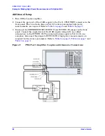
Page 28: ...required Refer to Table 1 on page 4 and Table 6 on page 9 3 Disconnect the REFERENCE SOURCE OUT and RCVR R1 IN jumper on the front panel Connect the coupled arm of the 20 dB coupler along with any added attenuation to the RCVR R1 IN The same instructions apply to Port 2 with one exception disconnect the jumper to RCVR R2 IN if high power measurements are required for the reverse parameters Refer t...

Page 29: ... clear the Auto Range box and type 10 dB into Atten Control for Port 1 Verify that Port Powers Coupled is checked to ensure that Ports 1 and Port 2 power levels are the same Press OK 2 Estimate the maximum amount of gain that could be provided by the DUT and as a result the maximum amount of power that could be received by Test Port 2 when the DUT is in compression For example if a DUT with a maxi...

Page 30: ...igh as 10 dBm Receiver B will be coupled to the analyzer RF path that could receive a maximum of 20 dBm from the DUT Analyzer coupler loss is 13 dB The optimum receiver power level is 12 dBm With the previous points in mind the amount of attenuation can be calculated from the following equations Fix Attenuator Fix Attenuator 2 Port One Way High Power Configuration Booster Amplifier RF INPUT RF OUT...

Page 31: ... B IN Figure 11 Receiver Attenuators CAUTION PNA Option 016 adds a 35 dB step attenuator with 5 dB resolution to A and B receivers Power measurements to Test Ports 1 and 2 above 35 dBm will require additional attenuation Add the appropriate amount of attenuation that will keep the coupler arm output power below the maximum receiver inputs Refer to Table 1 on page 4 to optimize the power levels in ...

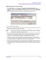
Page 32: ...e Setup Test Set Figure 12 Trace Chan 2 In the application window select External flow through R1 Loop Figure 13 R1 Input Path 3 Measure the output power at Test Port 1 using a power meter Verify the power measurement If you are measuring a highly reflective device a high power isolators should be inserted between the 20 dB coupler and CPLR THRU front panel ports to protect Port 1 Source ...

Page 33: ... down menu select Measure S21 Figure 14 Response Menu 3 To Perform a response calibration following steps a b c and d a Connect the test port cables of the analyzer to form a thru configuration b In the Response drop down menu select Cal Wizard see Figure 14 In the application window select UNGUIDED Calibration Response 1 port 2 port Use Mechanical Standards Next Figure 15 Unguided Calibration ...

Page 34: ...ide E8362 3 4C Option H85 Example Making High Power Measurements with Option H85 c Select Response Next Figure 16 Response d Select THRU Next Follow the analyzers window prompts to finish calibration Figure 17 THRU ...

Page 35: ...vels and the gain of the booster amplifier the attenuator setting must be taken into consideration If no calibration has been performed or if the instrument is in an un calibrated state the following must be taken into consideration when interpreting the measured data The value of attenuation added to receiver A and B The R channel reference level supplied from the coupler arm of the 20 dB coupler...

Page 36: ...F Cable Port 1 CPLR THRU to A25 Test Port 1 Coupler E8364 20073 W642 2 W64 replaces W56 A39 and W84 E8362C RF Cable Port 2 CPLR THRU to A26 Test Port 1 Coupler E8362 20019 W642 E8363 4C RF Cable Port 2 CPLR THRU to A26 Test Port 1 Coupler E8364 20074 All User s Guide E8364 90040 All Overlay for Option H85 E8364 80013 Delete A38 A39 E8362C Bias tee with cable 5086 7239 A38 A39 E8363 4C Bias tee wit...

Page 37: ... in a tightly closed container It is extremely flammable In case of fire use alcohol foam dry chemical or carbon dioxide water may be ineffective Use isopropyl alcohol with adequate ventilation and avoid contact with eyes skin and clothing It causes skin irritation may cause eye damage and is harmful if swallowed or inhaled It may be harmful if absorbed through the skin Wash thoroughly after handl...

Page 38: ...side of the ac power supply Cautions applicable to this instrument CAUTION Always use the three prong ac power cord supplied with this instrument Failure to ensure adequate earth grounding by not using this cord can cause instrument damage CAUTION This product is designed for use in Installation Category II and Pollution Degree 2 per IEC 61010 Second Edition and 664 respectively CAUTION This instr...

Page 39: ...onductor inside or outside the product is likely to make the product dangerous Intentional interruption is prohibited WARNING These servicing instructions are for use by qualified personnel only WARNING The opening of covers or removal of parts is likely to expose dangerous voltages Disconnect the instrument from all voltage sources while it is being opened WARNING This product is designed for use...

Page 40: ...ymbol indicates that the power line switch is in the OFF position This symbol is used to identify a terminal which is internally connected to the product frame or chassis The CE mark is a registered trademark of the European Community If accompanied by a year it is when the design was proven The CSA mark is a registered trademark of the Canadian Standards Association This instrument complies with ...

Page 41: ... complies with the German FTZ 526 527 Radiated Emissions and Conducted Emission requirements Compliance with German Noise Requirements This is to declare that this instrument is in conformance with the German Regulation on Noise Declaration for Machines Laermangabe nach der Maschinenlaermrerordnung 3 GSGV Deutschland Acoustic Noise Emission Geraeuschemission LpA 70 dB Lpa 70 dB Operator Position a...

Page 42: ... handling components and assemblies or when making connections always wear a heel strap 9300 1126 when working in an area with a conductive floor If you are uncertain about the conductivity of your floor wear a heel strap always ground yourself before you clean inspect or make a connection to a static sensitive device or test port You can for example grasp the grounded outer shell of the test port...

Page 43: ...ent field engineer NOTE In any correspondence or telephone conversation refer to the Agilent product by its model number and full serial number With this information the Agilent representative can determine whether your product is still within its warranty period Shipping Your Analyzer to Agilent for Service or Repair IMPORTANT Agilent Technologies reserves the right to reformat or replace the int...

Page 44: ...38 User s Guide E8362 3 4C Option H85 Agilent Support and Assistance ...

Reviews: