Installation Note E8362-90016
23
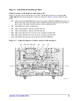
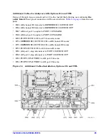
Additional Cables for Analyzers with Options 014 and UNL
Using a 5/16-inch torque wrench set to 10 in-lbs, install the following new cables
in the
order listed
. Front panel connectors will be secured later.
Table 1 on page 4
lists the new
parts.
• W65 A23 channel R1 detector to REFERENCE 1 SOURCE OUT
• W66 A24 channel R2 detector to REFERENCE 2 SOURCE OUT
• W67 A25 test port 1 coupler to PORT 1 CPLR ARM
• W68 A26 test port 2 coupler to PORT 2 CPLR ARM
• W69 PORT 1 RCVR A IN to A27 channel A mixer
• W70 REFERENCE 1 RCVR R1 IN to A28 channel R1 mixer
• W71 REFERENCE 2 RCVR R2 IN to A29 channel R2 mixer
• W72 PORT 2 RCVR B IN to A30 channel B mixer
• W81 A36 port 1 step attenuator to PORT 1 SOURCE OUT
• W82 A37 port 2 step attenuator to PORT 2 SOURCE OUT
• W83 PORT 1 CPLR THRU to A38 port 1 bias tee
• W84 PORT 2 CPLR THRU to A39 port 2 bias tee
Figure 16
Additional Cables Installation, Options 014 and UNL


