Service Guide E8364-90001
4- 33
PNA Series Microwave Network Analyzers
Troubleshooting
E8362A, E8363A, E8364A
Measurement System Troubleshooting
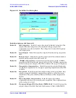
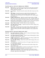
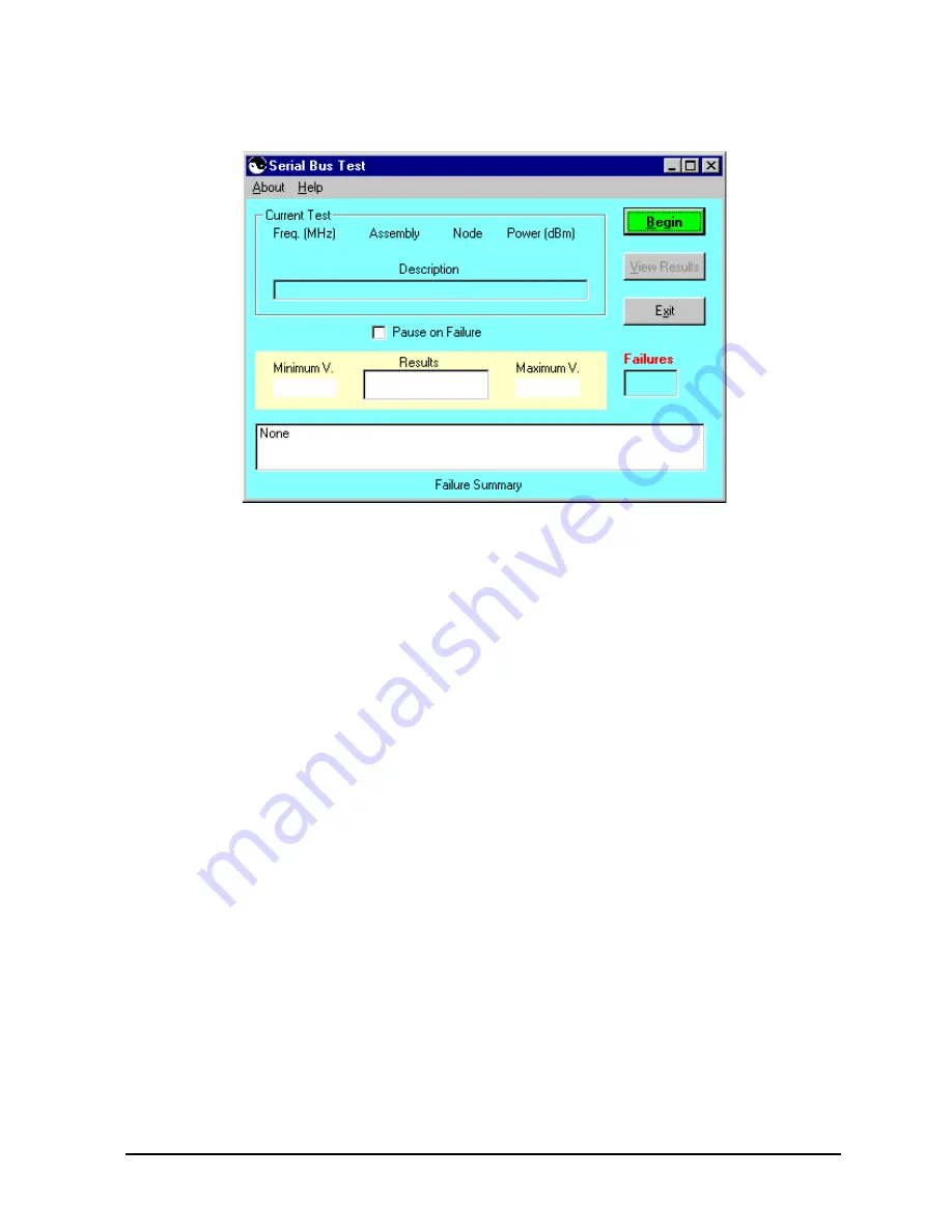
Figure 4-10 Serial Bus Test Dialog Box
Node Descriptions, A12 Source 20
Node 111
ALC integrator
Node 111 senses the output of the ALC integrator. The
output of the ALC integrator is the combined voltage output of all
compensation circuits in the ALC. The voltage level varies with frequency
and output power.
Node 112
Level Output
Node 112 senses the output of the detector log amp in the
ALC.
Node
113
Detector Level
Node 113 senses the power level of the internal detector
signal from the output of the A12 source 20.
Node
114
−
1V/GHz Compensation
Node 114 senses the inverse of the
−
1V/GHz
signal that comes from the A11 phase lock board. The
−
1V/GHz compensates
for first-order power changes of the YIG oscillator with respect to frequency.
Node
115
Temperature Compensation
Node 115 senses the output of thermistor
circuity that compensates for changes in operating temperature of the YIG
oscillator.
Node
116
Power DAC
Node 116 senses the output voltage of the power DAC. This
output is summed with other compensation signals to control the source
output level. The power DAC has the most influence of the compensation
signals.
Node
117
Power Amplifier Compensation
Node 117 senses the voltage
compensation for the source output power amplifiers. This compensation is
set for each source band.
Node
118
Permanent Magnet YIG Oscillator (PMYO) DAC
Node 118 senses the
output voltage of the DAC that sets the frequency of the 3.8 GHz PMYO.
Summary of Contents for E8362A
Page 11: ...Service Guide E8364 90001 1 1 1 Safety and Regulatory Information ...
Page 19: ...Service Guide E8364 90001 2 1 2 General Product Information ...
Page 29: ...Service Guide E8364 90001 3 1 3 Tests and Adjustments ...
Page 79: ...Service Guide E8364 90001 4 1 4 Troubleshooting ...
Page 139: ...Service Guide E8364 90001 5 1 5 Theory of Operation ...
Page 169: ...Service Guide E8364 90001 6 1 6 Replaceable Parts ...
Page 215: ...Service Guide E8364 90001 7 1 7 Repair and Replacement Procedures ...
Page 287: ...Service Guide E8364 90001 A 1 A Error Terms ...
Page 303: ...Service Guide E8364 90001 B 1 B Option Enable Utility ...
Page 309: ...Service Guide E8364 90001 C 1 C Firmware Upgrades ...
Page 313: ...Service Guide E8364 90001 D 1 D Operating System Recovery ...

