3-34
Service Guide E8364-90001
Tests and Adjustments
PNA Series Microwave Network Analyzers
Performance Tests (Agilent N2721A Software Package)
E8362A, E8363A, E8364A
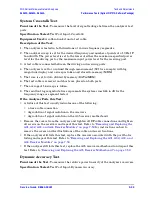
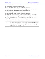
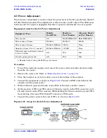
8. The mean of the points on the trace, in watts, is read: (
P
lin
).
9. Average power in dBm is calculated:
P
dBm
=
10
∗
Log10(P
lin
∗
1000)
.
10. Corrected noise floor in dBm for a 10 Hz IF bandwidth =
P
dBm
−
19.96 dB
−
(5.00-P
log
)
.
If the Analyzer Fails this Test:
• A failure of this test indicates a failure of one or more of the following assemblies.
• A31 channel A receiver
• A34 channel B receiver
• A6 SPAM board
• Since all four receivers are identical, the channel A and channel B receivers can be
swapped with the channel R1 and channel R2 receivers to determine if they are the
cause of the failure. Refer to
“Removing and Replacing the A31, A32, A33, and A34
Receiver Modules” on page 7-50
. After swapping the receivers, repeat this test.
• If the analyzer still fails this test, replace the A6 SPAM board and repeat this test.
Refer to
“Removing and Replacing the A6, A8, and A10 Boards” on page 7-18
.
Calibration Coefficient Test
Function of the Test:
To verify the uncorrected calibration coefficients of your analyzer.
The calibration coefficients are measured in forward and reverse direction. Refer to
for error term information relating to the calibration
coefficients measured.
Specification Tested:
Uncorrected System Performance
Equipment Used:
A calibration kit and a test cable.
Description of the Test:
1. A series of 2-port calibrations are performed. Two full SOLT 2-port calibrations are
performed on each port. Isolation is turned off during each 2-port calibration.
2. A test cable is attached to the first port, and a calibration is performed at the end of the
cable and at the second port. The cable is moved to the second port and another
calibration is performed. Using two calibrations helps to eliminate the unknown
characteristics of the through cable.
3. Each calibration produces 12 error terms.
4. The error terms are used to determine the following characteristics: directivity, source
match, load match, reflection tracking, and transmission tracking.
If the Analyzer Fails this Test:
• If the analyzer fails tracking error terms only, perform
and repeat this test.
• Failure of any other error terms indicate a hardware failure. Refer to the appropriate
error term discussion in
for a typical cause of failure. Refer
to
Chapter 7, “Repair and Replacement Procedures,”
for instructions on replacing the
suspected faulty component or assembly.
Summary of Contents for E8362A
Page 11: ...Service Guide E8364 90001 1 1 1 Safety and Regulatory Information ...
Page 19: ...Service Guide E8364 90001 2 1 2 General Product Information ...
Page 29: ...Service Guide E8364 90001 3 1 3 Tests and Adjustments ...
Page 79: ...Service Guide E8364 90001 4 1 4 Troubleshooting ...
Page 139: ...Service Guide E8364 90001 5 1 5 Theory of Operation ...
Page 169: ...Service Guide E8364 90001 6 1 6 Replaceable Parts ...
Page 215: ...Service Guide E8364 90001 7 1 7 Repair and Replacement Procedures ...
Page 287: ...Service Guide E8364 90001 A 1 A Error Terms ...
Page 303: ...Service Guide E8364 90001 B 1 B Option Enable Utility ...
Page 309: ...Service Guide E8364 90001 C 1 C Firmware Upgrades ...
Page 313: ...Service Guide E8364 90001 D 1 D Operating System Recovery ...


