6-22
Service Guide E8364-90001
Replaceable Parts
PNA Series Microwave Network Analyzers
Replaceable Parts Listings
E8362A, E8363A, E8364A
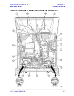
Bottom Hardware
Reference
Designator
Part
Number
Qty
Description
➀
E8364-00002
2
Detector/attenuator/bias tee bracket
(Used on standard instrument and all options.)
➁
E8364-20115
1
mixer bracket
➂
E8364-60008
1
mixer bias board
➃
0515-0430
9
Machine screw M3.0 x 6, pan head
(Detector brackets-3 ea; front-panel LED board-3)
➄
0515-0372
12
Machine screw M3.0 x 8, pan head
(A35-2; A20-2; A36/A37-2 ea; mixer bracket-4)
➅
0515-0374
15
Machine screw M3.0 x 10, pan head
(A17-4; A18-4; A16-5; A22-2)
➆
0515-0664
2
Machine screw M3.0 x 12, pan head
(A19-2)
➇
0515-0666
37
Machine screw M3.0 x 18, pan head
(A35 casting-13; A20-4; A27–A30-4 ea;
A23/A24-2 ea: E8363A/E8364A only)
➈
0515-0667
4
Machine screw M3.0 x 25, pan head
(A21-4: E8363A/E8364A only)
➉
0515-1349
12
Machine screw M3.0 x 30, pan head
(A31–A34-3 ea)
0515-2141
4
Machine screw M2.5 x 14, pan head
(A38/A39-2 ea)
08720-60182
1
Front-panel LED board
5022-1087
2
Test port coupler nut
1400-3014
2
Cable clamp
8364-0007
1
Shield, hard disk drive
11
12
13
14
15
Summary of Contents for E8362A
Page 11: ...Service Guide E8364 90001 1 1 1 Safety and Regulatory Information ...
Page 19: ...Service Guide E8364 90001 2 1 2 General Product Information ...
Page 29: ...Service Guide E8364 90001 3 1 3 Tests and Adjustments ...
Page 79: ...Service Guide E8364 90001 4 1 4 Troubleshooting ...
Page 139: ...Service Guide E8364 90001 5 1 5 Theory of Operation ...
Page 169: ...Service Guide E8364 90001 6 1 6 Replaceable Parts ...
Page 215: ...Service Guide E8364 90001 7 1 7 Repair and Replacement Procedures ...
Page 287: ...Service Guide E8364 90001 A 1 A Error Terms ...
Page 303: ...Service Guide E8364 90001 B 1 B Option Enable Utility ...
Page 309: ...Service Guide E8364 90001 C 1 C Firmware Upgrades ...
Page 313: ...Service Guide E8364 90001 D 1 D Operating System Recovery ...


