A-14
Service Guide E8364-90001
Error Terms
PNA Series Microwave Network Analyzers
Error Term Data
E8362A, E8363A, E8364A
Transmission Tracking (E
TF
and E
TR
)
Transmission tracking is the difference between the frequency response of the reference
path (including the R input) and the frequency response of the transmission test path
(including the A or B input) while measuring transmission. The response of the test port
cables is included. These terms are characterized by measuring the transmission (S
21
, S
12
)
of the “thru” configuration during the measurement calibration.
All transmission measurements are affected by transmission tracking errors.
Typical Cause of Failure
The
test port cable
is the most common cause of transmission tracking specification failure.
If the test port cable performance has been independently verified, suspect the following:
• If both E
TF
and E
TR
fail
— suspect the analyzer
switch splitter
• If one of the track term specification fails
— suspect the
coupler, step attenuator, or the test receiver
of the failed port
To troubleshoot, refer to
“Checking the Receiver Group” on page 4-50
or to
Signal Separation Group” on page 4-46
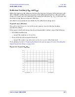
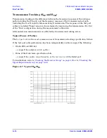
Figure A-7 Typical E
TF
/E
TR
Summary of Contents for E8362A
Page 11: ...Service Guide E8364 90001 1 1 1 Safety and Regulatory Information ...
Page 19: ...Service Guide E8364 90001 2 1 2 General Product Information ...
Page 29: ...Service Guide E8364 90001 3 1 3 Tests and Adjustments ...
Page 79: ...Service Guide E8364 90001 4 1 4 Troubleshooting ...
Page 139: ...Service Guide E8364 90001 5 1 5 Theory of Operation ...
Page 169: ...Service Guide E8364 90001 6 1 6 Replaceable Parts ...
Page 215: ...Service Guide E8364 90001 7 1 7 Repair and Replacement Procedures ...
Page 287: ...Service Guide E8364 90001 A 1 A Error Terms ...
Page 303: ...Service Guide E8364 90001 B 1 B Option Enable Utility ...
Page 309: ...Service Guide E8364 90001 C 1 C Firmware Upgrades ...
Page 313: ...Service Guide E8364 90001 D 1 D Operating System Recovery ...


