7-26
Service Guide E8364-90026
Repair and Replacement Procedures
PNA Series Microwave Network Analyzers
Removing and Replacing the A14 System Motherboard
E8362B, E8363B, E8364B
Removing and Replacing the A14 System Motherboard
Tools Required
• T-10 TORX driver (set to 9 in-lb)
• T-20 TORX driver (set to 21 in-lb)
• 5/16-inch open-end torque wrench (set to 10 in-lb)
• ESD grounding wrist strap
Removal Procedure
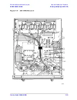
Refer to
for this procedure.
1. Disconnect the power cord.
2. Remove the outer and inner covers. Refer to
“Removing the Covers” on page 7-6
3. Remove the front panel assembly. Refer to
“Removing and Replacing the Front Panel
.
4. Remove the A12 source 20. Refer to
“Removing and Replacing the A12 Source 20” on
.
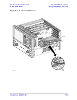
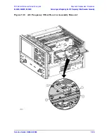
5. Remove the A13 (Option 080) frequency offset receiver assembly, if present. Refer to
“Removing and Replacing the A13 Frequency Offset Receiver Assembly” on page 7-24
.
6. Remove the A11 phase lock board. Refer to
“Removing and Replacing the A11 Phase
.
7. Remove the A4 power supply assembly. Refer to
“Removing and Replacing the A4
Power Supply Assembly” on page 7-16
8. Remove the card cage boards (A6, A8, and A10). Remove A9 (Option 080), if present.
Refer to
“Removing and Replacing the A6, A8, A9, and A10 Boards” on page 7-18
.
9. Remove the A15 CPU board. Refer to
“Removing and Replacing the A15 CPU Board” on
.
10. Remove the Midweb. Refer to
“Removing and Replacing the Midweb and the B1 Fan”
.
11. Disconnect the front panel ribbon cable (item
①
), the A40 floppy disk drive ribbon cable
(item
②
), the A16 test set motherboard ribbon cable (item
③
), and the USB hub
assembly cable (item
④
) from the A14 system motherboard.
12. Lift the tab (item
⑤
) at the rear of the A40 floppy disk drive enclosure and remove the
rear enclosure cover.
13. Remove the four screws (item
⑥
) that secure the A14 system motherboard.
14. Lift the A14 system motherboard out of the analyzer.
Replacement Procedure
1. Reverse the order of the removal procedure.
2. Perform the post-repair adjustments, verifications, and performance tests that pertain
to this removal procedure. Refer to
Summary of Contents for E8362B
Page 11: ...Service Guide E8364 90026 1 1 1 Safety and Regulatory Information ...
Page 19: ...Service Guide E8364 90026 2 1 2 General Product Information ...
Page 33: ...Service Guide E8364 90026 3 1 3 Tests and Adjustments ...
Page 83: ...Service Guide E8364 90026 4 1 4 Troubleshooting ...
Page 151: ...Service Guide E8364 90026 5 1 5 Theory of Operation ...
Page 185: ...Service Guide E8364 90026 6 1 6 Replaceable Parts ...
Page 269: ...Service Guide E8364 90026 7 1 7 Repair and Replacement Procedures ...
Page 351: ...Service Guide E8364 90026 8 1 8 General Purpose Maintenance Procedures ...

