4-10
Service Guide E8364-90026
Troubleshooting
PNA Series Microwave Network Analyzers
Power Up Troubleshooting
E8362B, E8363B, E8364B
If All Supply Voltages Are Missing
WARNING
Disconnect the line-power cord before removing any assembly.
Procedures described in this document may be performed with
power supplied to the product while protective covers are removed.
Energy available at many points may, if contacted, result in personal
injury or loss of life.
It is necessary to sequentially remove all of the assemblies, taking care to disconnect the
line-power cord before each removal, and then to measure the supply voltages after each
removal.
If the missing supply voltages return to a “power on” condition after removal of an
assembly, suspect that assembly as being defective.
Remove the network analyzer assemblies in the order specified in the following steps (refer
to
for removal instructions).
1. Unplug the test set motherboard cable from the A16 test set motherboard.
2. Unplug the front panel interface cable from the A3 front panel interface board.
3. Remove the A6 SPAM board.
4. Remove the A8 fractional-N synthesizer board.
5. Remove the A10 frequency reference board.
6. Remove the A11 phase lock board.
7. Unplug the A30 floppy disk drive from the A14 system motherboard.
8. Unplug the A31 hard disk drive from the A15 CPU board.
The minimum required assemblies to power up the analyzer are:
• A4 power supply
• A14 system motherboard
• A15 CPU board
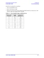
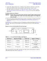
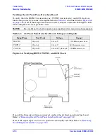
To further isolate the failure in the three remaining assemblies, measure the resistance on
the extender board (with the power turned off) from the power supply test points to “GND”.
Refer to
. The voltages should be as shown in
NOTE
Make sure that the only assemblies plugged in are the three minimum
required assemblies listed above.
Check for shorts (zero
Ω
) or very low resistance (approximately 1
Ω
). If a short or low
resistance is measured, isolate each of the remaining three boards in the following order,
and recheck the shorted test point after each board is removed. Note that the resistance
may be different from that listed in the table, but you should be able to determine if the
shorted condition has changed.
Summary of Contents for E8362B
Page 11: ...Service Guide E8364 90026 1 1 1 Safety and Regulatory Information ...
Page 19: ...Service Guide E8364 90026 2 1 2 General Product Information ...
Page 33: ...Service Guide E8364 90026 3 1 3 Tests and Adjustments ...
Page 83: ...Service Guide E8364 90026 4 1 4 Troubleshooting ...
Page 151: ...Service Guide E8364 90026 5 1 5 Theory of Operation ...
Page 185: ...Service Guide E8364 90026 6 1 6 Replaceable Parts ...
Page 269: ...Service Guide E8364 90026 7 1 7 Repair and Replacement Procedures ...
Page 351: ...Service Guide E8364 90026 8 1 8 General Purpose Maintenance Procedures ...


