background image

Page 4 of 10 


E8364B-07A 


c.


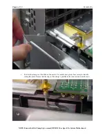
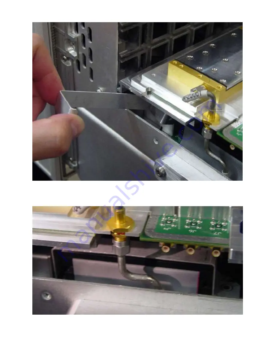
Position the clamp over the Ribbon Connector. Use needle nose pliers if necessary to slide the 
clamp into place. Ensure that the edge of the clamp is parallel to the connector and not skewed. 


NOTE: Ensure that the Clamp Lip is secured BELOW the edge of the System Motherboard 

Summary of Contents for E8362BH85PNA Series

Page 1: ...of the instrument This Service Note must go along together with the instrument model Service Guide during modification AGILENT TECHNOLOGIES INC 2009 PRINTED IN U S A December 2 2009 Rev 16 Page 1 of 10 E8364B 07A S E R V I C E N O T E Supersedes E8364B 07 E8364B PNA Series RF Network Analyzers Serial Numbers MY00000000 MY43040911 Add on mechanical components to enhance instrument reliability This ...

Page 2: ...es can not vibrate loose from their connectors during extreme handling Solution Action Enhancement No 1 Applies to all Options 1 Required Tool for Ribbon Cable Clamp a Gather a standard 10 lb in breakaway wrench used for semi rigid cables b Remove the open end head by loosening set screw It will be replaced with L Key shown below c Secure and orient the L Key to the breakaway handle 2 Ribbon Cable...

Page 3: ...Page 3 of 10 E8364B 07A b Insert Ribbon Cable Clamp under Source Assembly as shown ...

Page 4: ...r the Ribbon Connector Use needle nose pliers if necessary to slide the clamp into place Ensure that the edge of the clamp is parallel to the connector and not skewed NOTE Ensure that the Clamp Lip is secured BELOW the edge of the System Motherboard ...

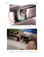
Page 5: ...ge 5 of 10 E8364B 07A d Using tweezers install a new 0515 0374 screw through the hole in the bracket e Use a nut runner tool T 316130 or alternatively a clean erasure end of a pencil to help run the screw ...

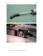
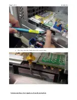
Page 6: ...Page 6 of 10 E8364B 07A f Secure screw using the modified 10 lb in breakaway wrench ...

Page 7: ...Page 7 of 10 E8364B 07A g This image shows the final position of the secured clamp Enhancement Issue No 2 Applies to all models and options ...

Page 8: ... at 9 lb in This Retainer Clip may naturally rotate a bit when being secured which is acceptable Note that the existing screw needs to be removed and discarded prior installing Retainer Clip 1 shown below in Figure 2a 2b and 3 Figure 1 Clip Retainer E8361 20067 And Flat Head Screw 0515 1644 Figure 2a Figure 2b ...

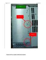
Page 9: ...Page 9 of 10 E8364B 07A Enhancement No 3 Applies to all models and options Figure 3 Retainer 1 Retainer 2 ...

Page 10: ...e used in 2 places and secured at 9 lb in These parts will replace existing screw 0515 0374 used in Step 3 and Step 4 as shown in Figure 2 to secure the Phase Lock Board E8364 60137 Figure 1 Patch Lock Screw 0515 2799 And Flat Washer 3050 0891 Figure 2 Step 2 and Step 4 Step 1 and Step 3 ...

Reviews: