5-16
Service Guide E8364-90038
Theory of Operation
PNA Series Microwave Network Analyzers
Signal Separation Group Operation
E8362C, E8363C, E8364C
Signal Separation Group Operation
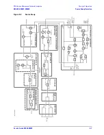
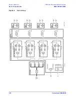
The signal separation group divides the source signal into a reference path and a test path. Refer to
Figure
5-3 on page 5-17
.
•
The reference signal is transmitted to the receiver group.
•
The test signal is transmitted through—and reflected from—the device under test (DUT) and then is
transmitted to the receiver group.
•
Control lines to this group are routed from the A16 test set motherboard.
In this section, the following assemblies are described:
•
A22 Switch Splitter
•
A25 and A26 Test Port Couplers
•
A23 and A24 Detectors (E8363C and E8364C Only)
•
30-dB Fixed Attenuators (E8362C Only)
•
A36 and A37 60-dB Source Step Attenuators (Option UNL)
•
A38 and A39 Bias Tees (Option UNL)
•
A43 and A44 35-dB Receiver Step Attenuators (Option 016)
•
Front Panel Jumpers (
Option 014 Configurable Test Set
)
A22 Switch Splitter
For the E8363C and E8364C, the output of the A21 SOMA 50 is routed to the A22 switch splitter. For the
E8362C, this is the output of the A12 source 20 assembly. The A22 switch splitter is a solid-state switch. It
switches between the Port 1 and Port 2 measurement paths, automatically enabling alternate forward and
reverse measurements. The A22 switch splitter provides an internal termination for the measurement port
that is inactive.
Each measurement path in the A22 switch splitter includes a two-way splitter; the signal is split into the test
port signal and the receiver signal.
The test port signal is sent directly through the test port coupler, A25 or A26, and out through either PORT 1
or PORT 2 to the DUT, unless Option UNL is installed. In this case, the signal is routed through the step
attenuator, A36 or A37, the bias tee, A38 or A39, then through the test port coupler and test port to the DUT.
The reference signal is routed to the appropriate R channel receiver module, A32 or A33, through a detector,
A23 or A24 (for E8363C and E8364C), or a 30-dB fixed attenuator (for E8362C), and a receiver first converter,
A28 or A29. If Option 014 is installed, the signal is routed through a front-panel channel R jumper to the
receiver first converter.
Summary of Contents for E8362C
Page 11: ...Service Guide E8364 90038 1 1 1 Safety and Regulatory Information ...
Page 21: ...Service Guide E8364 90038 2 1 2 General Product Information ...
Page 33: ...Service Guide E8364 90038 3 1 3 Tests and Adjustments ...
Page 81: ...Service Guide E8364 90038 4 1 4 Troubleshooting ...
Page 137: ...Service Guide E8364 90038 5 1 5 Theory of Operation ...
Page 171: ...Service Guide E8364 90038 6 1 6 Replaceable Parts ...
Page 257: ...Service Guide E8364 90038 7 1 7 Repair and Replacement Procedures ...
Page 341: ...Service Guide E8364 90038 8 1 8 General Purpose Maintenance Procedures ...


