7-22
Service Guide E8364-90038
Repair and Replacement Procedures
PNA Series Microwave Network Analyzers
Removing and Replacing the A12 Source 20
E8362C, E8363C, E8364C
Removing and Replacing the A12 Source 20
Tools Required
•
T-10 TORX driver (set to 9 in-lb)
•
T-20 TORX driver (set to 21 in-lb)
•
5/16-inch open-end torque wrench (set to 10 in-lb)
•
ESD grounding wrist strap
Removal Procedure
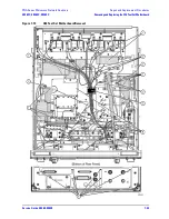
Refer to
Figure 7-9
for this procedure.
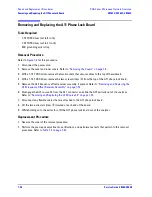
1. Disconnect the power cord.
2. Remove the outer and inner covers. Refer to
“Removing the Covers” on page 7-6
.
3. Remove the A13 (Option 080) frequency offset receiver assembly, if present. Refer to
“Removing and
Replacing the A13 Frequency Offset Receiver Assembly” on page 7-24
.
4. With a 5/16-inch torque wrench, disconnect the semirigid cable (item
①
) from the bottom of the A12
source 20.
CAUTION
To avoid damage to the semirigid cable (item
①
), pull down on the cable from the bottom of
the analyzer to move it away while sliding out the A12 source 20. The cable has some spring
to it and the RF pin could be damaged by the A12 source 20.
5. Disengage the A12 source 20 from the A11 connector and slide out of the analyzer. Observe the
CAUTION
above.
Replacement Procedure
1. Reverse the order of the removal procedure.
2. Perform the post-repair adjustments, verifications, and performance tests that pertain to this removal
procedure. Refer to
Table 7-2 on page 7-82
.
Summary of Contents for E8362C
Page 11: ...Service Guide E8364 90038 1 1 1 Safety and Regulatory Information ...
Page 21: ...Service Guide E8364 90038 2 1 2 General Product Information ...
Page 33: ...Service Guide E8364 90038 3 1 3 Tests and Adjustments ...
Page 81: ...Service Guide E8364 90038 4 1 4 Troubleshooting ...
Page 137: ...Service Guide E8364 90038 5 1 5 Theory of Operation ...
Page 171: ...Service Guide E8364 90038 6 1 6 Replaceable Parts ...
Page 257: ...Service Guide E8364 90038 7 1 7 Repair and Replacement Procedures ...
Page 341: ...Service Guide E8364 90038 8 1 8 General Purpose Maintenance Procedures ...

