Installation Note E8364-90012
13
Step 5. Install the Option 014 Cables
CAUTION
Use a 5/16-in torque wrench set to 10 in-lbs on all cable connections in this step
of the procedure.
Analyzers without Option UNL
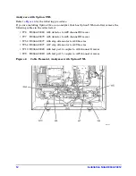
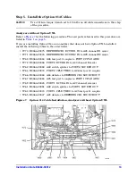
Refer to
for the following procedure. The new parts referenced in this procedure are
listed in
If you are installing Option 014 on an analyzer that does not have Option UNL installed,
install the following cables in the order listed.:
• W70 E8364-20075 REFERENCE 1 RCVR R1 IN to A28 channel R1 mixer
• W71 E8364-20076 REFERENCE 2 RCVR R2 IN to A29 channel R2 mixer
• W68 E8364-20044 A26 test port 2 coupler to PORT 2 CPLR ARM
• W72 E8364-20046 PORT 2 RCVR B IN to A30 channel B mixer
• W62 E8364-20082 A22 switch splitter to PORT 2 SOURCE OUT
• W64 E8364-20074 PORT 2 CPLR THRU to A26 test port 2 coupler
• W66 E8364-20048 A24 detector to REFERENCE 2 SOURCE OUT
• W67 E8364-20043 A25 test port 1 coupler to PORT 1 CPLR ARM
• W69 E8364-20045 PORT 1 RCVR A IN to A27 channel A mixer
• W61 E8364-20081 A22 switch splitter to PORT 1 SOURCE OUT
• W63 E8364-20073 PORT 1 CPLR THRU to A25 test port 1 coupler
• W65 E8364-20047 A23 detector to REFERENCE 1 SOURCE OUT
Figure 7
Option 014 Cable Installation, Analyzers without Option UNL

