background image

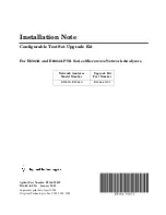
Installation Note E8364-90012                                                                                                                         


3

Getting Assistance from Agilent

By internet, phone, or fax, get assistance with all your test and measurement needs.

This information supersedes all prior HP contact information.

Online assistance:

www.agilent.com/find/assist

Americas

Brazil

(tel)

 (+55) 11 3351 7012

(fax) 

(+55) 11 3351 7024

Canada

(tel)

 +1 877 894 4414

(fax) 

+1 303 662 3369

Mexico

(tel)

 1 800 254 2440

(fax)

 1 800 254 4222

United States

(tel)


800 829 4444

(alt)


(+1) 303 662 3998

(fax)


800 829 4433

Asia Pacific and Japan

Australia

(

tel

) 1 800 225 574

(

fax

) 1 800 681 776

(

fax

) 1 800 225 539

China

(

tel

) 800 810 0508

(

alt

) 800 810 0510

(

fax

) 800 810 0507

(

fax

) 800 810 0362

Hong


Kong

(

tel

) 800 933 229

(

fax

) 800 900 701

India

(tel) 

1600 112 626

(

fax

) 1600 112 727

(

fax

) 1600 113 040

Japan (Bench)

(

tel

) 0120 32 0119

(

alt

) (+81) 426 56 7799

(

fax

) 0120 01 2144

Japan (On-Site)

(

tel

) 0120 802 363

(

alt

) (+81) 426 56 7498

(

fax

) (+81) 426 60 8953

Singapore

(

tel

) 1 800 275 0880

(

fax

) (+65) 6755 1235

(

fax

) (+65) 6755 1214

South Korea

(

tel

) 080 778 0011

(

fax

) 080 778 0013

Taiwan

(

tel

) 0800 047 669

(

fax

) 0800 047 667

(

fax

) 886 3492 0779

Thailand

(

tel

) 1 800 2758 5822

(

alt

) (+66) 2267 5913

(

fax

) 1 800 656 336

Malaysia

(

tel

) 1800 880 399

(

fax

) 1800 801 054

Europe

Austria

(

tel

) 0820 87 44 11*

(

fax

) 0820 87 44 22

Belgium

(

tel

) (+32) (0)2 404 9340

(

alt

) (+32) (0)2 404 9000

(

fax

) (+32) (0)2 404 9395

Denmark

(tel

) (+45) 7013 1515

(

alt

) (+45) 7013 7313

(

fax

) (+45) 7013 1555

Finland

(

tel

) (+358) 10 855 2100

(

fax

) (+358) (0) 10 855 2923

France

(

tel

) 0825 010 700*

(

alt

) (+33) (0)1 6453 5623

(

fax

) 0825 010 701*

Germany

(

tel

) 01805 24 6333*

(

alt

) 01805 24 6330*

(

fax

) 01805 24 6336*

Ireland

(tel

) (+353) (0)1 890 924 204

(

alt

) (+353) (0)1 890 924 206

(

fax

)(+353) (0)1 890 924 024

Israel

(tel

) (+972) 3 9288 500

(

fax

) (+972) 3 9288 501

Italy

(

tel

) (+39) (0)2 9260 8484

(

fax

) (+39) (0)2 9544 1175

Luxemburg

(

tel

) (+32) (0)2 404 9340

(

alt

) (+32) (0)2 404 9000

(

fax

) (+32) (0)2 404 9395

Netherlands

(

tel

) (+31) (0)20 547 2111

(

alt

) (+31) (0)20 547 2000

(

fax

) (+31) (0)20 547 2190

Russia

(

tel

) (+7) 095 797 3963

(

alt

) (+7) 095 797 3900

(

fax

) (+7) 095 797 3901

Spain

(

tel

) (+34) 91 631 3300

(

alt

) (+34) 91 631 3000

(

fax

) (+34) 91 631 3301

Sweden

(

tel

) 0200 88 22 55*

(

alt

) (+46) (0)8 5064 8686

(

fax

) 020 120 2266*

Switzerland (French)

(

tel

) 0800 80 5353 opt. 2*

(

alt

) (+33) (0)1 6453 5623

(

fax

) (+41) (0)22 567 5313

Switzerland (German)

(

tel

) 0800 80 5353 opt. 1*

(

alt

) (+49) (0)7031 464 6333

(

fax

) (+41) (0)1 272 7373

Switzerland (Italian)

(

tel

) 0800 80 5353 opt. 3*

(

alt

) (+39) (0)2 9260 8484

(

fax

) (+41) (0)22 567 5314

United Kingdom

(

tel

) (+44) (0)7004 666666

(

alt

) (+44) (0)7004 123123

(

fax

) (+44) (0)7004 444555

(tel) 

= primary telephone number;

 (alt) 

= alternate telephone number;

 (fax) 

= FAX number; * = in country number 

11/16/04

Summary of Contents for E8363A

Page 1: ...persedes print date April 2004 Agilent Technologies Inc 2002 2004 2005 Installation Note Configurable Test Set Upgrade Kit For E8363A and E8364A PNA Series Microwave Network Analyzers Network Analyzer Model Number Upgrade Kit Part Number E8363A E8364A E8364 60101 ...

Page 2: ...al item as defined in FAR 2 101 a or as Restricted computer software as defined in FAR 52 227 19 June 1987 or any equivalent agency regulation or contract clause Use duplication or disclosure of Software is subject to Agilent Technologies standard commercial license terms and non DOD Departments and Agencies of the U S Government will receive no greater than Restricted Rights as defined in FAR 52 ...

Page 3: ...399 fax 1800 801 054 Europe Austria tel 0820 87 44 11 fax 0820 87 44 22 Belgium tel 32 0 2 404 9340 alt 32 0 2 404 9000 fax 32 0 2 404 9395 Denmark tel 45 7013 1515 alt 45 7013 7313 fax 45 7013 1555 Finland tel 358 10 855 2100 fax 358 0 10 855 2923 France tel 0825 010 700 alt 33 0 1 6453 5623 fax 0825 010 701 Germany tel 01805 24 6333 alt 01805 24 6330 fax 01805 24 6336 Ireland tel 353 0 1 890 924...

Page 4: ...s the external amplifier s frequency response and drift to be ratioed out For high dynamic range measurements front panel jumpers are moved to reverse the signal path through one of the couplers This allows for a 15 dB improvement in transmitted signal sensitivity in one direction only These jumpers are installed on both ports allowing the user to choose a high dynamic range measurement in either ...

Page 5: ...N to A30 channel B mixer 1 E8364 20046 The following parts are required for only analyzers without Option UNL installed Lower front panel overlay Option 014 1 E8364 80004 W61 RF cable A22 switch splitter to PORT 1 SOURCE OUT 1 E8364 20081 W62 RF cable A22 switch splitter to PORT 2 SOURCE OUT 1 E8364 20082 W63 RF cable PORT 1 CPLR THRU to A25 test port 1 coupler 1 E8364 20073 W64 RF cable PORT 2 CP...

Page 6: ...hin the network analyzer Static electricity can build up on your body and can easily damage sensitive internal circuit elements when discharged Static discharges too small to be felt can cause permanent damage To prevent damage to the instrument always wear a grounded wrist strap having a 1 MΩ resistor in series with it when handling components and assemblies always use a grounded conductive table...

Page 7: ... connections except the front panel connectors to which the front panel jumpers attach Use a 5 16 in torque wrench set to 21 in lbs for these connections Equipment Required for Post Upgrade Adjustments Description Qty Part Number T 10 TORX driver set to 9 in lbs 1 N A T 20 TORX driver set to 21 in lbs 1 N A 5 16 in torque wrench set to 10 in lbs 1 N A 5 16 in torque wrench set to 21 in lbs 1 N A E...

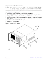
Page 8: ...anel assemblies Refer to Figure 2 for this procedure 1 Disconnect the power cord if it has not already been disconnected 2 With a T 20 TORX driver remove the strap handles item by loosening the screws item on both ends until the handle is free of the analyzer 3 With a T 20 TORX driver remove the four rear panel feet item by removing the center screws item 4 Slide the four bottom feet item off the ...

Page 9: ...ight screws item from the sides of the frame CAUTION Before removing the front panel from the analyzer lift and support the front of the analyzer chassis 2 Slide the front panel over the test port connectors 3 Disconnect the front panel interface ribbon cable item The front panel is now free from the analyzer Figure 3 Front Panel Assembly Removal ...

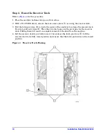
Page 10: ...item towards the center of the analyzer to release the receiver deck Be sure to pull only item The other two latch pins are the pivot pins for the receiver deck Pulling them will result in complete removal of the deck from the analyzer 4 Lift the receiver deck to partially raise it then release the latch pin item Lift the receiver deck to its fully raised position and ensure that the latch pin lat...

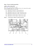
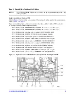
Page 11: ... following cables in the order listed W7 E8364 20025 A23 detector to A28 channel R1 mixer W8 E8364 20026 A24 detector to A29 channel R2 mixer W9 E8364 20019 A25 test port 1 coupler to A27 channel A mixer W10 E8364 20020 A26 test port 2 coupler to A30 channel B mixer W5 E8364 20021 A22 switch splitter to A25 test port 1 coupler W6 E8364 20022 A22 switch splitter to A26 test port 2 coupler Figure 5 ...

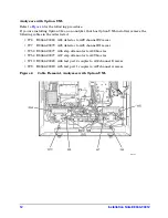
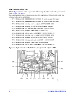
Page 12: ...ables in the order listed W8 E8364 20080 A24 detector to A29 channel R2 mixer W7 E8364 20079 A23 detector to A28 channel R1 mixer W53 E8364 20077 A36 step attenuator to A38 bias tee W54 E8364 20077 A37 step attenuator to A39 bias tee W10 E8364 20020 A26 test port 2 coupler to A30 channel B mixer W9 E8364 20019 A25 test port 1 coupler to A27 channel A mixer Figure 6 Cable Removal Analyzers with Opt...

Page 13: ...nel R1 mixer W71 E8364 20076 REFERENCE 2 RCVR R2 IN to A29 channel R2 mixer W68 E8364 20044 A26 test port 2 coupler to PORT 2 CPLR ARM W72 E8364 20046 PORT 2 RCVR B IN to A30 channel B mixer W62 E8364 20082 A22 switch splitter to PORT 2 SOURCE OUT W64 E8364 20074 PORT 2 CPLR THRU to A26 test port 2 coupler W66 E8364 20048 A24 detector to REFERENCE 2 SOURCE OUT W67 E8364 20043 A25 test port 1 coupl...

Page 14: ...R2 mixer W68 E8364 20044 A26 test port 1 coupler to PORT 2 CPLR ARM W72 E8364 20046 PORT 2 RCVR B IN to A30 channel B mixer W82 E8364 20054 A37 step attenuator to PORT 2 SOURCE OUT W84 E8364 20040 PORT 2 CPLR THRU to A39 bias tee W66 E8364 20048 A24 detector to REFERENCE 2 SOURCE OUT W67 E8364 20043 A25 test port 1 coupler to PORT 1 CPLR ARM W69 E8364 20045 PORT 1 RCVR A IN to A27 channel A mixer ...

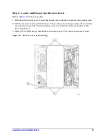
Page 15: ...r of the analyzer to release the receiver deck 2 Lift the receiver deck to partially lower it then release the latch pin item Lower the receiver deck to its fully lowered position and ensure that the latch pin latches in the lowered position 3 With a T 10 TORX driver install the four screws item to secure the receiver deck Figure 9 Receiver Deck Lowering ...

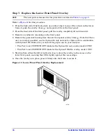
Page 16: ...nel 4 Remove the protective backing from the new front panel overlay item Note that there are two overlays provided one for Option 014 only and one for Option 014 in combination with Option UNL Make sure you install the proper one for your analyzer The Port 1 and 2 SOURCE OUT labels for the Option 014 only overlay reads 40 VDC The Port 1 and 2 SOURCE OUT labels for the Option UNL 014 overlay reads...

Page 17: ...t to 21 in lbs 2 Reconnect the ribbon cable item to the A3 front panel interface board 3 Slide the front panel over the test port connectors being careful to align the power switch and floppy disk drive to their corresponding front panel cutouts Ensure that the ribbon cable is located below the fan to prevent it from being damaged by the fan blades 4 With a T 10 TORX driver install the eight screw...

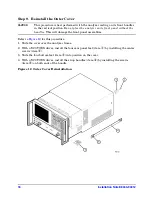
Page 18: ...dles This will damage the front panel assemblies Refer to Figure 12 for this procedure 1 Slide the cover over the analyzer frame 2 With a T 20 TORX driver install the four rear panel feet item by installing the center screws item 3 Slide the four bottom feet item into position on the cover 4 With a T 20 TORX driver install the strap handles item by installing the screws item on both ends of the ha...

Page 19: ...e 2 In the Select Desired Option list click 014 Configurable Test Set 3 Click Enable 4 Click Yes in answer to the displayed question in the Restart Analyzer box 5 When the installation is complete click Exit Verify that Option 014 is Enabled 1 On the analyzer s Help menu click About Network Analyzer 2 Verify that 014 is listed after Options in the display 3 Click OK NOTE If Option 014 has not been...

Page 20: ...nalyzer should now operate and phase lock over its entire frequency range If you experience difficulty with the basic functioning of the analyzer contact Agilent Refer to Getting Assistance from Agilent on page 3 Although the analyzer functions its performance relative to its specifications has not been verified for the additional frequency range enabled by this upgrade It is recommended that a fu...

Reviews: