background image

4


Installation Note E8364-90024

Items Included in the Upgrade Kit

Check the contents of your kit against this list. If any item is missing or damaged, contact 
Agilent Technologies. Refer to 

“Contacting Agilent” on page 3

.

Table 1

Contents of the Upgrade Kit (E8364-60107)

Ref.

Desig.

Description

Qty

 Part 

Number

These parts are for all analyzer options

Installation note (this document)

1

E8364-90024

Machine screw, M3.0 x 6, TORX T-10 (for attaching switch 
bracket)

2

0515-0430

Machine screw, M3.0 x 12, TORX T-10 (for attaching A45 and A46 
reference switches)

8

0515-0664

Switch bracket

1

E8364-00012

A23

Detector

1

5087-7242

A45, A46

Reference switch

2

5087-7238

Wiring harness, two conductors (for A45 and A46 switches)

2

8121-0966

W95

RF cable, A46 reference switch to A23 channel R1 detector

1

E8364-20119

W96

RF cable, A45 reference switch to A46 reference switch

1

E8364-20127

W97

RF cable, A46 reference switch to REFERENCE 1 SOURCE OUT

1

E8364-20121

W98

RF cable, A45 reference switch to REFERENCE 1 RCVR R1 IN

1

E8364-20123

These parts are for analyzers WITH Options 014 and 080 but WITHOUT Options UNL and 016

W67

RF cable, A25 test port 1 coupler to PORT 1 CPLR ARM

1

E8364-20156

W68

RF cable, A26 test port 2 coupler to PORT 2 CPLR ARM

1

E8364-20157

W71

RF cable, REFERENCE 2 RCVR R2 IN to A29 channel R2 mixer

1

E8364-20153

W99

RF cable, A45 reference switch to A28 channel R1 mixer

1

E8364-20152

These parts are for analyzers WITH Options UNL, 014, and 080 but WITHOUT Option 016

W71

RF cable, REFERENCE 2 RCVR R2 IN to A29 channel R2 mixer

1

E8364-20155

W99

RF cable, A45 reference switch to A28 channel R1 mixer

1

E8364-20154

This part is for analyzers with Options UNL, 014, 016, and 080

W99

RF cable, A45 reference switch to A28 channel R1 mixer

1

E8364-20125

Summary of Contents for E8363B

Page 1: ...nt date September 2007 Agilent Technologies Inc 2002 2005 2007 Installation Note Reference Mixer Transfer Switch Upgrade Kit For E8363B C and E8364B C PNA Series Microwave Network Analyzers Network Analyzer Model Number Upgrade Kit Part Number E8363B C and E8364B C E8364 60107 ...

Page 2: ...al item as defined in FAR 2 101 a or as Restricted computer software as defined in FAR 52 227 19 June 1987 or any equivalent agency regulation or contract clause Use duplication or disclosure of Software is subject to Agilent Technologies standard commercial license terms and non DOD Departments and Agencies of the U S Government will receive no greater than Restricted Rights as defined in FAR 52 ...

Page 3: ...not have the proper options as listed below it will be necessary to install those options BEFORE installing this option Option 081 Description of the Option 081 Reference Mixer Transfer Switch Upgrade This upgrade adds two high speed microwave switches in the reference R1 channel of the PNA These switches are used to switch a reference mixer in and out of the reference channel signal path during c...

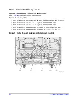
Page 4: ...tor 1 E8364 20119 W96 RF cable A45 reference switch to A46 reference switch 1 E8364 20127 W97 RF cable A46 reference switch to REFERENCE 1 SOURCE OUT 1 E8364 20121 W98 RF cable A45 reference switch to REFERENCE 1 RCVR R1 IN 1 E8364 20123 These parts are for analyzers WITH Options 014 and 080 but WITHOUT Options UNL and 016 W67 RF cable A25 test port 1 coupler to PORT 1 CPLR ARM 1 E8364 20156 W68 R...

Page 5: ...nternal circuit elements when discharged Static discharges too small to be felt can cause permanent damage To prevent damage to the instrument always wear a grounded wrist strap having a 1 MΩ resistor in series with it when handling components and assemblies always use a grounded conductive table mat while working on the instrument always wear a heel strap when working in an area with a conductive...

Page 6: ... in lbs on all cable connections except the front panel connectors to which the front panel jumpers attach Option 014 Use a 5 16 inch torque wrench set to 21 in lbs for these connections Equipment Required for Post Upgrade Adjustments Description Qty Agilent Part Number T 10 TORX driver set to 9 in lbs 1 N A T 20 TORX driver set to 21 in lbs 1 N A 5 16 inch torque wrench set to 10 in lbs 1 N A 5 1...

Page 7: ...has not already been disconnected 2 With a T 20 TORX driver remove the four rear panel feet item by removing the center screws item 3 Slide the four bottom feet item off the cover 4 With a T 20 TORX driver remove the strap handles item by loosening the screw item on each end until the handle is free of the analyzer 5 Slide the cover off of the frame Figure 2 Outer Cover Removal NOTE The figure abo...

Page 8: ... the front panel from the analyzer lift and support the front of the analyzer chassis 3 Slide the front panel over the test port connectors 4 Disconnect the front panel interface ribbon cable item from the A3 front panel interface board The front panel is now free from the analyzer Figure 3 Front Panel Assembly Removal NOTE The figure above shows the E8363 4B front panel and floppy disk drive The ...

Page 9: ...ver remove the four screws item that secure the receiver deck 3 Pull the latch pin item towards the other side of the analyzer to release the receiver deck 4 Lift the receiver deck to partially raise it then release the latch pin item Lift the receiver deck to its fully raised position and ensure that the latch pin latches in the raised position Figure 4 Receiver Deck Raising ...

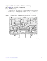
Page 10: ...llowing cables W65 E8364 20047 A23 channel R1 detector to REFERENCE 1 SOURCE OUT W67 E8364 20043 A25 test port 1 coupler to PORT 1 CPLR ARM W68 E8364 20044 A26 test port 2 coupler to PORT 2 CPLR ARM W70 E8364 20075 REFERENCE 1 RCVR R1 IN to A28 channel R1 mixer W71 E8364 20076 REFERENCE 2 RCVR R2 IN to A29 channel R2 mixer Figure 5 Cable Removal Analyzers with Options 014 and 080 ...

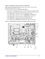
Page 11: ...his portion of the procedure Remove the following cables W65 E8364 20047 A23 channel R1 detector to REFERENCE 1 SOURCE OUT W70 E8364 20176 REFERENCE 1 RCVR R1 IN to A28 channel R1 mixer W71 E8364 20177 REFEFENCE 2 RCVR R2 IN to A29 channel R2 mixer Figure 6 Cable Removal Analyzers with Options UNL 014 and 080 ...

Page 12: ...and 080 Refer to Figure 7 for this portion of the procedure Remove the following cables W65 E8364 20047 Channel R1 detector to REFERENCE 1 SOURCE OUT W70 E8364 20151 REFERENCE 1 RCVR R1 IN to A28 channel R1 mixer Figure 7 Cable Removal Analyzers with Options UNL 014 016 and 080 ...

Page 13: ...ol cable item and the flexible RF cable item from the detector 3 With a T 10 TORX driver remove the two mounting screws item and remove the detector from the analyzer 4 Place the new detector provided into position With a T 10 TORX driver install the two mounting screws item to secure the detector 5 Using a 5 16 inch torque wrench connect cable W3 to the new detector 6 Reconnect the stranded contr...

Page 14: ...isted in Table 1 on page 4 1 Attach one of the reference switches provided to the mounting bracket item provided using four M3 0 x 12 screws provided 2 Insert the bracket with the A45 reference switch attached into the location shown 3 With a T 10 TORX driver install two M3 0 x 6 mounting screws item provided in the bracket to secure it to the test set deck Figure 9 A45 Reference Switch Installati...

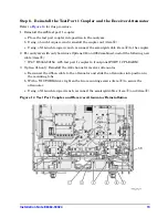
Page 15: ... mounting screws item and slide the attenuator toward the rear of the analyzer to remove it from the mounting tabs c Disconnect the ribbon cable from the attenuator and set the attenuator aside for reinstallation later 2 Remove the A25 test port 1 coupler a Using a 5 16 inch wrench disconnect the semirigid cables item and item if not previously removed b Using a 1 inch wrench remove the coupler nu...

Page 16: ... J31 Wire harness 8121 0966 A46 reference switch to A16 test set motherboard J30 W96 E8364 20127 A45 reference switch to A46 reference switch W97 E8364 20121 A46 reference switch to REFERENCE 1 SOURCE OUT W98 E8364 20123 A45 reference switch to REFERENCE 1 RCVR R1 IN W99 E8364 20152 A45 reference switch to A28 channel R1 mixer W95 E8364 20119 A46 reference switch to A23 channel R1 detector W68 E83...

Page 17: ...t motherboard J31 Wire harness 8121 0966 A46 reference switch to A16 test set motherboard J30 W96 E8364 20127 A45 reference switch to A46 reference switch W97 E8364 20121 A46 reference switch to REFERENCE 1 SOURCE OUT W98 E8364 20123 A45 reference switch to REFERENCE 1 RCVR R1 IN W99 E8364 20154 A45 reference switch to A28 channel R1 mixer W95 E8364 20119 A46 reference switch to channel R1 detecto...

Page 18: ...ference switch to A16 test set motherboard J31 Wire harness 8121 0966 A46 reference switch to A16 test set motherboard J30 W96 E8364 20127 A45 reference switch to A46 reference switch W97 E8364 20121 A46 reference switch to REFERENCE 1 SOURCE OUT W98 E8364 20123 A45 reference switch to REFERENCE 1 RCVR R1 IN W99 E8364 20125 A45 reference switch to A28 channel R1 mixer W95 E8364 20119 A46 reference...

Page 19: ...pler 2 For analyzers with only hardware Options 014 and 080 combined install the following new cable item W67 E8364 20156 A25 test port 1 coupler to front panel PORT 1 CPLR ARM 3 Option 016 only Reinstall the A43 channel A receiver attenuator a Reconnect the ribbon cable to the attenuator and slide the attenuator into position in the mounting tabs b With a T 10 TORX driver tighten the two mounting...

Page 20: ...ide of the analyzer to release the receiver deck 2 Lift the receiver deck to partially lower it then release the latch pin item Lower the receiver deck to its fully lowered position and ensure that the latch pin latches in the lowered position 3 With a T 10 TORX driver install the four screws item to secure the receiver deck Figure 15 Receiver Deck Lowering ...

Page 21: ...nch lbs 2 Reconnect the ribbon cable item to the A3 front panel interface board 3 Slide the front panel over the test port connectors being careful to align the power switch and floppy disk drive to their corresponding front panel cutouts Ensure that the ribbon cable item is located below the fan to prevent it from being damaged by the fan blades 4 With a T 10 TORX driver install the eight screws ...

Page 22: ...s front handles in the vertical position Do not place the analyzer on its front panel without the handles This will damage the front panel assemblies Refer to Figure 17 for this procedure 1 Slide the cover over the analyzer frame 2 With a T 20 TORX driver install the four rear panel feet item by installing the center screws item 3 Slide the four bottom feet item into position on the cover 4 With a...

Page 23: ...ired Option list click 081 Reference Transfer Switch 3 Click Enable 4 Click Yes in answer to the displayed question in the Restart Analyzer box 5 When the installation is complete click Exit Verify that Option 081 is Enabled 1 On the analyzer s Help menu click About Network Analyzer 2 Verify that 081 is listed after Options in the display 3 Click OK when done NOTE If Option 081 has not been enable...

Page 24: ...on The analyzer should now operate and phase lock over its entire frequency range If you experience difficulty with the basic functioning of the analyzer contact Agilent Refer to Contacting Agilent on page 3 Although the analyzer functions its performance relative to its specifications has not been verified for the additional frequency range enabled by this upgrade It is recommended that a full in...

Reviews: