Installation Note E8364-90011
13
Step 5. Install the Attenuators and Bias Tees
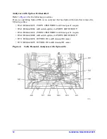
Refer to
for this portion of the procedure.
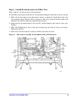
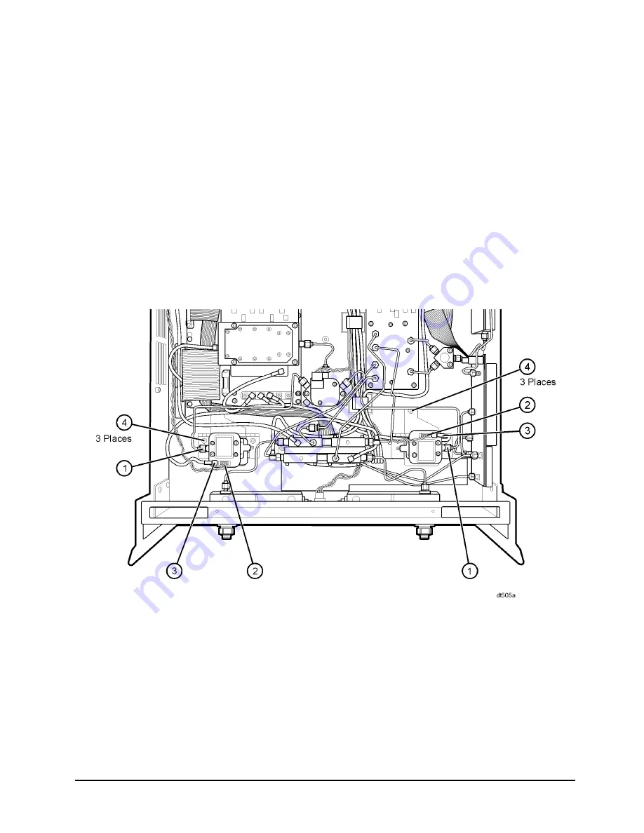
To install the attenuators and bias tees, the brackets holding the detectors must be removed.
1. With a 5/16-inch torque wrench, disconnect, remove, and keep for reinstallation later, the
two semirigid cables (item
①
) from each detector. Note: For analyzers without Option 014
installed, one of these cables has already been removed.
2. Disconnect the stranded control cable (item
②
) and the flexible cable (item
③
) from each
detector.
3. With a T-10 TORX driver, remove the three mounting screws (item
④
) from each bracket
holding the detector.
4. Remove the brackets from the analyzer with the detectors attached.
Figure 7
Attenuator and Bias Tee Installation, Bracket Removal


