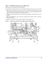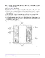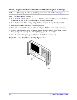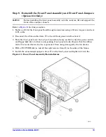
16
Installation Note E8364-90011
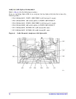
Analyzers with Option 014 Installed
for the following procedure. The new parts referenced in this procedure are
listed in
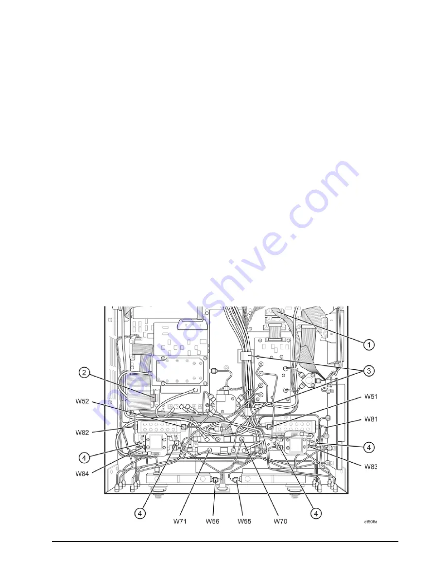
1. If you are installing Option UNL on an analyzer that has Option 014 installed, install the
following cables in the order listed:
• Ribbon cable
①
8121-0819 A36 step attenuator to A16 motherboard
(P1 SRC ATT)
• Ribbon cable
②
8121-0119 A37 step attenuator to A16 motherboard
(P2 SRC ATT)
• W52 E8364-20056 A22 switch splitter to A37 step attenuator
• W51 E8364-20055 A22 switch splitter to A36 step attenuator
• W71 E8364-20050 RCVR R2 IN to A29 channel R2 mixer
• W70 E8364-20049 RCVR R1 IN to A28 channel R1 mixer
• W56 E8364-20052 A39 bias tee to A26 test port 2 coupler
• W55 E8364-20051 A38 bias tee to A25 test port 1 coupler
• W82 E8364-20054 A37 step attenuator to PORT 2 SOURCE OUT
• W84 E8364-20040 PORT 2 CPLR THRU to A39 bias tee
• W81 E8364-20053 A36 step attenuator to PORT 1 SOURCE OUT
• W83 E8364-20039 PORT 1 CPLR THRU to A38 bias tee
2. Route the bias tee control cables through the cable clamps, (item
③
), to the rear of the
analyzer for connection to the A16 motherboard later.
3. Reinstall the semirigid cables, (item
④
), to the detectors.
Figure 10 Option UNL Cable Installation, Analyzers with Option 014

