background image

Installation Note E8801-90024

5

Getting Assistance from Agilent

By internet, phone, or fax, get assistance with all your test and measurement needs.

Table 2

Contacting Agilent

Online assistance:

www.agilent.com/find/assist

United States
(tel) 1 800 452 4844

Latin America
(tel) (305) 269 7500
(fax) (305) 269 7599

Canada
(tel) 1 877 894 4414
(fax) (905) 282-6495

Europe
(tel) (+31) 20 547 2323
(fax) (+31) 20 547 2390

Australia
(tel) 1 800 629 485
(fax) (+61) 3 9210 5947

New Zealand
(tel) 0 800 738 378
(fax) (+64) 4 495 8950

Japan
(tel) (+81) 426 56 7832
(fax) (+81) 426 56 7840

Singapore
(tel) 1 800 375 8100
(fax) (65) 836 0252

Malaysia
(tel) 1 800 828 848
(fax) 1 800 801 664

India
(tel) 1 600 11 2929
(fax) 000 800 650 1101

Hong Kong
(tel) 800 930 871
(fax) (852) 2506 9233

Taiwan
(tel) 0800 047 866
(fax) (886) 2 25456723

Philippines
(tel) (632) 8426802
(tel) (PLDT subscriber only)
1 800 16510170
(fax) (632) 8426809
(fax) (PLDT subscriber only)
1 800 16510288

Thailand
(tel) (outside Bangkok)
(088) 226 008
(tel) (within Bangkok)
(662) 661 3999
(fax) (66) 1 661 3714

People’s Republic of China
(tel) (preferred)
800 810 0189
(tel) (alternate)
10800 650 0021
(fax) 10800 650 0121

Summary of Contents for E8801-60103

Page 1: ...24 Printed in USA December 2001 Installation Note Configurable Test Set Upgrade Kit For PNA Series RF Network Analyzers E8801A E8802A and E8803A Network Analyzer Model Number Upgrade Kit Part Number E8801A E8802A E8803A E8801 60103 ...

Page 2: ...o this material including but not limited to the implied warranties of merchantability and fitness for a particular purpose Agilent shall not be liable for errors contained herein or for incidental or consequential damages in connection with the furnishing performance or use of this material Copyright 2001 Agilent Technologies Inc All rights reserved ...

Page 3: ...e external amplifier s frequency response and drift to be ratioed out There are also internal step attenuators between the coupler and the receivers to prevent receiver overload For high dynamic range measurements front panel jumpers are moved to reverse the signal path through one of the couplers This allows for a 15 dB improvement in transmitted signal sensitivity in one direction only These jum...

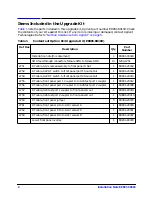
Page 4: ...t panel R Out 1 E8801 20002 W52 RF cable A22 RF switch to front panel port 1 Source Out 1 E8801 20004 W54 RF cable A22 RF switch to front panel port 2 Source Out 1 E8801 20010 W55 RF cable front panel port 1 Coupler In to A24 test port 1 coupler 1 E8801 20012 W56 RF cable front panel port 2 Coupler In to A26 test port 2 coupler 1 E8801 20008 W57 RF cable A24 test port 1 coupler to front panel A ou...

Page 5: ...47 New Zealand tel 0 800 738 378 fax 64 4 495 8950 Japan tel 81 426 56 7832 fax 81 426 56 7840 Singapore tel 1 800 375 8100 fax 65 836 0252 Malaysia tel 1 800 828 848 fax 1 800 801 664 India tel 1 600 11 2929 fax 000 800 650 1101 Hong Kong tel 800 930 871 fax 852 2506 9233 Taiwan tel 0800 047 866 fax 886 2 25456723 Philippines tel 632 8426802 tel PLDT subscriber only 1 800 16510170 fax 632 8426809...

Page 6: ...hin the network analyzer Static electricity can build up on your body and can easily damage sensitive internal circuit elements when discharged Static discharges too small to be felt can cause permanent damage To prevent damage to the instrument always wear a grounded wrist strap having a 1 MΩ resistor in series with it when handling components and assemblies always use a grounded conductive table...

Page 7: ...ment Required for the Installation CAUTION Use a 5 16 in torque wrench set to 10 in lbs on all SMA cable connections except the front panel SMA feed through connectors to which the front panel jumpers attach Use a 5 16 in torque wrench set to 21 in lbs for these connections Description Qty Part Number T 10 TORX driver set to 9 in lbs 1 N A T 20 TORX driver set to 21 in lbs 1 N A 5 16 in torque wre...

Page 8: ...anel assemblies Refer to Figure 2 for this procedure 1 Disconnect the power cord if it has not already been disconnected 2 With a T 20 TORX driver remove the strap handles item by loosening the screws item on both ends until the handle is free of the analyzer 3 With a T 20 TORX driver remove the four rear panel feet item by removing the center screws item 4 Slide the four bottom feet item off the ...

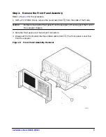
Page 9: ...six screws item from the sides of the frame CAUTION Before removing the front panel from the analyzer lift and support the front of the analyzer chassis 2 Slide the front panel over the test port connectors 3 Disconnect the front panel interface ribbon cable item The front panel is now free from the analyzer Figure 3 Front Panel Assembly Removal ...

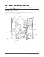
Page 10: ...Instrument Cables CAUTION Use a 5 16 in torque wrench set to 10 in lbs on all SMA cable connections in this step of the procedure Refer to Figure 4 for this procedure 1 Remove and discard the following cables W2 W3 W4 W5 W6 and W7 Figure 4 Standard Cable Removal ...

Page 11: ...nt panel jumpers attach Use a 5 16 in torque wrench set to 21 in lbs for these connections Refer to Figure 5 for this procedure The new parts referenced in this procedure are listed in Table 1 on page 4 1 Install ten SMA feed through connectors item in the front chassis holes provided 2 Install cables W51 W52 and W57 3 Install cables W55 W61 and W62 4 Install cables W54 and W59 5 Install cables W5...

Page 12: ...e frame to push the overlay and separate it from the front panel b From the front side of the front panel pull the overlay completely off and discard it c Remove any adhesive remaining on the front panel 2 Remove the protective backing from the new Option 014 front panel overlay 3 Starting from either the left or right side loosely place the overlay in the recess on the lower front panel ensuring ...

Page 13: ...re 7 for this procedure 1 Connect the front panel interface ribbon cable item 2 Slide the front panel over the test port connectors being careful to align the power switch and floppy disk drive to their corresponding front panel cutouts Ensure that the ribbon cable is located below the fan to prevent it from being damaged by the fan blades 3 With a T 10 TORX driver install the six screws item in t...

Page 14: ...ndles This will damage the front panel assemblies Refer to Figure 8 for this procedure 1 Slide the cover over the analyzer frame 2 With a T 20 TORX driver install the four rear panel feet item by installing the center screws item 3 Slide the four bottom feet item into position on the cover 4 With a T 20 TORX driver install the strap handles item by installing the screws item on both ends of the ha...

Page 15: ...uestion in the Restart Analyzer box 5 When the installation is complete click Exit Front Panel Keys Procedure 1 In the COMMAND block press Menu Dialog 2 In the NAVIGATION block press the Right Tab and Arrows to move over to the System menu and down to the Service selection Press the Right Tab to display the extended menu and the Arrows to select Option Enable Press Click 3 Tab to the Select Desire...

Page 16: ...bled perform step 8 again If the option is still not enabled contact Agilent Technologies Refer to Getting Assistance from Agilent on page 5 Front Panel Keys Procedure 1 In the COMMAND block press Menu Dialog 2 In the NAVIGATION block press the Right Tab and Arrows to move over to the Help menu and down to the About Network Analyzer selection Press Click 3 Verify that 014 is listed after Options i...

Reviews: