background image

SYSTem Subsystem
SYSTem:COMMunicate:SERial:TRANsmit:PARity[:TYPE] EVEN|ODD|ZE-
RO|ONE|NONE

11-24

Agilent E4416A/E4417A Programming Guide

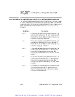
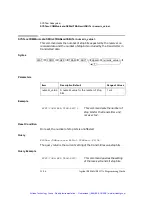
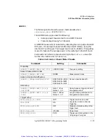
SYSTem:COMMunicate:SERial:TRANsmit:PARity[:TYPE] EVEN|ODD|ZERO|ONE|NONE 

This command decides what type of parity checking (if any) will take place 
on received data and also decides what parity (if any) will be included with 
transmitted data. The following choices are available and can be set using 
either this command or the equivalent 

[:RECeive]:PARity[:TYPE]


command.

Parity Type

Description

EVEN

The receiver expects a parity bit. All data received 
is checked for even parity. An error is generated if 
this test fails. Transmitted data includes a parity 
bit set for even parity indication.

ODD

The receiver expects a parity bit. All data received 
is checked for odd parity. An error is generated if 
this test fails. Transmitted data includes a parity 
bit set for odd parity indication.

ZERO

The receiver expects a parity bit. All data received 
has the parity checked and if it is not a logic low 
an error will be generated. Transmitted data 
includes a parity bit that is always set low (stick 0 
parity).

ONE

The receiver expects a parity bit. All data received 
has the parity checked and if it is not a logic high 
an error will be generated. Transmitted data 
includes a parity bit that is always set high (stick 
1 parity).

NONE

The receiver is not expecting a parity bit included 
in received data and does not perform a parity 
check. The transmitter does not include a parity 
bit in the transmitted data.

Artisan Technology Group - Quality Instrumentation ... Guaranteed | (888) 88-SOURCE | www.artisantg.com

Summary of Contents for EPM-P Series

Page 1: ...l service in house repair center WE BUY USED EQUIPMENT Sell your excess underutilized and idle used equipment We also offer credit for buy backs and trade ins www artisantg com WeBuyEquipment REMOTE INSPECTION Remotely inspect equipment before purchasing with our interactive website at www instraview com LOOKING FOR MORE INFORMATION Visit us on the web at www artisantg com for more information on ...

Page 2: ...nt Technologies Part no E4416 90029 November 2008 Programming Guide Agilent Technologies EPM P Series Power Meters Artisan Technology Group Quality Instrumentation Guaranteed 888 88 SOURCE www artisantg com ...

Page 3: ...ent Technologies All rights reserved Reproduction adaptation or translation without prior written permission is prohibited except as allowed under the copyright laws Printed in Malaysia Artisan Technology Group Quality Instrumentation Guaranteed 888 88 SOURCE www artisantg com ...

Page 4: ...ss I product provided with a protective earthing ground incorporated in the power cord The mains plug shall only be inserted in a socket outlet provided with a protective earth contact Any interruption of the protective conductor inside or outside the instrument is likely to make the instrument dangerous Intentional interruption is prohibited If this instrument is not used as specified the protect...

Page 5: ...contact Any interruption of the protective grounding conductor inside or outside the instrument or disconnection of the protective earth terminal can result in personal injury Caution Any adjustments or service procedures that require operation of the instrument with protective covers removed should be performed only by trained service personnel User Environment The product is suitable for indoor ...

Page 6: ...r explains how to use the CALibration command subsystem to zero and calibrate the power meter Chapter 5 DISPlay Subsystem This chapter explains how the DISPlay subsystem is used to control the the selection and presentation of the windows used on the power meter s display Chapter 6 FORMat Subsystem This chapter explains how the FORMat subsystem is used to set a data format for transferring numeric...

Page 7: ...uage and query the SCPI version Chapter 12 TRACe Subsystem This chapter explains how to use the TRACe command subsystem to configure and read back the measured power trace Chapter 13 TRIGger Subsystem This chapter explains how the TRIGger command subsystem is used synchronize device actions with events Chapter 14 UNIT Subsystem This chapter explains how to use the UNIT command subsystem to set the...

Page 8: ...P Series Power Meters Programming Guide vii Appendix A This appendix contains information about the calibration factor block layout Artisan Technology Group Quality Instrumentation Guaranteed 888 88 SOURCE www artisantg com ...

Page 9: ...er s Guide Option ABF Italian Language User s Guide Option ABZ Japanese Language User s Guide Option ABJ Useful information on SCPI Standard Commands for Programmable Instruments can be found in A Beginner s Guide to SCPI which is available by ordering Agilent Part Number 5010 7166 The SCPI reference manuals which are available from SCPI Consortium 8380 Hercules Drive Suite P3 La Mesa CA 91942 USA...

Page 10: ...eference Calibration Factor 1 7 Making Measurements 1 8 Using MEASure 1 9 Using the CONFigure Command 1 14 Using the Lower Level Commands 1 23 Making Measurements on Wireless Communication Standards 1 24 Measuring GSM 1 24 Measuring EDGE 1 26 Measuring NADC 1 28 Measuring iDEN 1 31 Measuring Bluetooth 1 33 Measuring cdmaOne 1 35 Measuring W CDMA 1 37 Measuring cdma2000 1 39 Using Sensor Calibratio...

Page 11: ...s 1 68 Using Duty Cycle 1 68 Making the Measurement 1 68 Getting the Best Speed Performance 1 71 Measurement Rate 1 71 Sensor 1 72 Trigger Mode 1 72 Output Format 1 73 Units 1 74 Command Used 1 74 Fast Mode 1 74 How Measurements are Calculated 1 75 Status Reporting 1 76 The General Status Register Model 1 77 How to Use Registers 1 79 Status Registers 1 84 Using the Operation Complete Commands 1 94...

Page 12: ... 1 2 3 4 SCALar POWer AC RELative expected_value resolution source list 2 12 CONFigure 1 2 3 4 SCALar POWer AC DIFFerence expected_value resolution source list 2 14 CONFigure 1 2 3 4 SCALar POWer AC DIFFerence RELative expected_value resolution source list 2 16 CONFigure 1 2 3 4 SCALar POWer AC RATio expected_value resolution source list 2 18 CONFigure 1 2 3 4 SCALar POWer AC RATio RELative expect...

Page 13: ...Sure 1 2 3 4 SCALar POWer AC expected_value resolution source list 2 56 MEASure 1 2 3 4 SCALar POWer AC RELative expected_value resolution source list 2 58 MEASure 1 2 3 4 SCALar POWer AC DIFFerence expected_value resolution source list 2 60 MEASure 1 2 3 4 SCALar POWer AC DIFFerence RELative expected_value resolution source list 2 62 MEASure 1 2 3 4 SCALar POWer AC RATio expected_value resolution...

Page 14: ...ue 4 12 CALibration 1 2 ZERO AUTO boolean 4 14 CALibration 1 2 ZERO NORMal AUTO boolean 4 15 DISPlay Subsystem 5 1 DISPlay Subsystem 5 2 DISPlay CONTrast numeric_value 5 3 DISPlay ENABle boolean 5 5 DISPlay SCReen FORMat character_data 5 6 DISPlay WINDow 1 2 Commands 5 8 DISPlay WINDow 1 2 ANALog Commands 5 9 DISPlay WINDow 1 2 ANALog LOWer numeric_value 5 10 DISPlay WINDow 1 2 ANALog UPPer numeri...

Page 15: ...a numeric_value 7 20 MEMory TABLe Commands 7 22 MEMory TABLe FREQuency numeric_value numeric_value 7 23 MEMory TABLe FREQuency POINts 7 26 MEMory TABLe GAIN MAGNitude numeric_value numeric_value 7 27 MEMory TABLe GAIN MAGNitude POINts 7 29 MEMory TABLe MOVE character_data character_data 7 30 MEMory TABLe SELect character_data 7 31 OUTput Subsystem 8 1 OUTPut Subsystem 8 2 OUTPut RECorder 1 2 FEED ...

Page 16: ...Se2 CORRection CSET 1 CSET2 STATe boolean 9 27 SENSe 1 SENSe2 CORRection DCYCle GAIN3 Commands 9 29 SENSe 1 SENSe2 CORRection DCYCle GAIN3 INPut MAGNitude numeric_value 9 30 SENSe 1 SENSe2 CORRection DCYCle GAIN3 STATe boolean 9 33 SENSe 1 SENSe2 CORRection FDOFfset GAIN4 INPut MAGNitude 9 35 SENSe 1 SENSe2 CORRection GAIN2 Commands 9 36 SENSe 1 SENSe2 CORRection GAIN2 STATe boolean 9 37 SENSe 1 S...

Page 17: ...EASuring SUMMary 10 14 STATus OPERation SENSe SUMMary 10 15 STATus OPERation TRIGger SUMMary 10 16 STATus OPERation ULFail SUMMary 10 17 STATus PRESet 10 18 Questionable Register Sets 10 19 STATus QUEStionable 10 20 STATus QUEStionable CALibration SUMMary 10 21 STATus QUEStionable POWer SUMMary 10 22 SYSTem Subsystem 11 1 SYSTem Subsystem 11 2 SYSTem COMMunicate GPIB SELF ADDRess numeric_value 11 ...

Page 18: ...Preset Values 11 32 SYSTem REMote 11 60 SYSTem RINTerface GPIB RS232 RS422 11 61 SYSTem RWLock 11 62 SYSTem VERSion 11 63 TRACe Subsystem 12 1 TRACe Subsystem 12 2 TRACe 1 2 DATA character_data 12 3 TRACe 1 2 STATe boolean 12 5 TRACe 1 2 UNIT character_data 12 6 TRIGger Subsystem 13 1 TRIGger Subsystem 13 2 ABORt 1 2 13 3 INITiate Commands 13 4 INITiate 1 2 CONTinuous boolean 13 5 INITiate 1 2 IMM...

Page 19: ...nce numeric_value 15 5 SERVice BIST FPATH 1 2 STATe boolean 15 6 SERVice BIST TBASe STATe boolean 15 7 SERVice BIST TRIGger LEVel STATe 15 8 SERVice BIST TRIGger TEST 15 9 SERVice OPTion character_data 15 10 SERVice SENSor 1 2 CALFactor cal_factor_data 15 11 SERVice SENSor 1 2 CDATe 15 13 SERVice SENSor 1 2 CORRections STATe boolean 15 14 SERVice SENSor 1 2 CPLace 15 16 SERVice SENSor 1 2 FREQuenc...

Page 20: ...16 4 PPD 16 4 PPE 16 4 PPU 16 5 SDC 16 5 SPD 16 5 SPE 16 6 CLS 16 7 DDT arbitrary block program data string program data 16 8 ESE NRf 16 10 ESR 16 11 IDN 16 12 OPC 16 13 OPT 16 14 RCL NRf 16 15 RST 16 16 SAV NRf 16 17 SRE NRf 16 18 STB 16 20 TRG 16 22 TST 16 23 WAI 16 24 Calibration Factor Block Layout A 1 Calibration Factor Block Layout A 2 Artisan Technology Group Quality Instrumentation Guarant...

Page 21: ...Contents 12 EPM P Series Power Meters Programming Guide Artisan Technology Group Quality Instrumentation Guaranteed 888 88 SOURCE www artisantg com ...

Page 22: ...tus Registers 10 2 11 1 DEFault Power Meter Presets 11 32 11 2 GSM900 Power Meter Presets 11 36 11 3 GSM900 Power Meter Presets Window Measurement Settings 11 37 11 4 GSM900 Power Meter Presets For Secondary Channel Sensors 11 38 11 5 EDGE Power Meter Presets 11 39 11 6 EDGE Power Meter Presets Window Measurement Settings 11 40 11 7 EDGE Power Meter Presets For Secondary Channel Sensors 11 41 11 8...

Page 23: ... Meter Presets For Secondary Channel Sensors 11 53 11 20 CDMA2000 Power Meter Presets 11 54 11 21 CDMA2000 Power Meter Presets Window Measurement Settings 11 55 11 22 CDMA2000 Power Meter Presets For Secondary Channel Sensors 11 56 11 23 iDEN Power Meter Presets 11 57 11 24 iDEN Power Meter Presets Window Measurement Settings 11 58 11 25 iDEN Power Meter Presets For Secondary Channel Sensors 11 59...

Page 24: ... Checking Application 1 64 1 6 Limits Checking Results 1 65 1 7 Pulsed Signal 1 69 1 8 How Measurements are Calculated 1 75 1 9 Generalized Status Register Model 1 77 1 10 Typical Status Register Bit Changes 1 78 1 11 Status System 1 84 3 1 CALCulate Block 3 2 9 1 Averaged Readings 9 8 11 1 A Trace Display Of The Active Timeslots 11 42 Artisan Technology Group Quality Instrumentation Guaranteed 88...

Page 25: ...Contents 2 EPM P Series Power Meters Programming Guide Artisan Technology Group Quality Instrumentation Guaranteed 888 88 SOURCE www artisantg com ...

Page 26: ...1 Power Meter Remote Operation Artisan Technology Group Quality Instrumentation Guaranteed 888 88 SOURCE www artisantg com ...

Page 27: ... page 1 41 Using Frequency Dependent Offset Tables on page 1 51 Setting the Range Resolution and Averaging on page 1 58 Setting Offsets on page 1 62 Setting Measurement Limits on page 1 64 Measuring Pulsed Signals on page 1 68 END on page 1 70 Getting the Best Speed Performance on page 1 71 How Measurements are Calculated on page 1 75 Status Reporting on page 1 76 Saving and Recalling Power Meter ...

Page 28: ...t have a unique address You can set the power meter s address to any value between 0 and 30 The address is set to 13 when the power meter is shipped from the factory The address is stored in non volatile memory and does not change when the power meter is switched off or after a remote interface reset Your GPIB bus controller has its own address Avoid using the bus controller s address for any inst...

Page 29: ... P Series Power Meter User s Guide For remote operation use the following commands SYSTem COMMunicate SERial CONTrol DTR SYSTem COMMunicate SERial CONTrol RTS SYSTem COMMunicate SERial RECeive BAUD SYSTem COMMunicate SERial RECeive BITs SYSTem COMMunicate SERial RECeive PACE SYSTem COMMunicate SERial RECeive PARity TYPE SYSTem COMMunicate SERial RECeive SBITs SYSTem COMMunicate SERIal TRANsmit AUT...

Page 30: ... state it was in prior to the command being received When to Zero Zeroing of the power meter is recommended when a 50C change in temperature occurs when you change the power sensor every 24 hours prior to measuring low level signals For example 10 dB above the lowest specified power for your power sensor Calibration Calibration sets the gain of the power meter using a 50 MHz 1 mW calibrator as a t...

Page 31: ...o the power reference oscillator It turns the power reference oscillator on then after calibrating returns the power reference oscillator to the same state it was in prior to the command being received The calibration sequence consists of Zeroing the power meter CALibration 1 2 ZERO AUTO ONCE and calibrating the power meter CALibration 1 2 AUTO ONCE The query enters a number into the output buffer...

Page 32: ...or further information Examples a To enter a reference calibration factor of 98 7 for channel A you should use the following command CAL RCF 98 7PCT This overrides any RCF previously set by selecting a sensor calibration table b To automatically set the reference calibration factor you have to use a sensor calibration table as described in Using Sensor Calibration Tables on page 1 41 To select and...

Page 33: ...States An alternative method to program the power meter is to use the lower level commands The advantage of using the lower level commands over the CONFigure command is that they give you more precise control of the power meter As shown in Table 1 1 the CONFigure command presets various states in the power meter It may be likely that you do not want to preset these states Refer to Using the Lower ...

Page 34: ...g commands show a few examples of how to use the MEASure query to make a measurement It is advisable to read through these examples in order as they become increasingly more detailed These examples configure the power meter for a measurement as described in each individual example automatically place the power meter in the wait for trigger state internally trigger the power meter to take one readi...

Page 35: ...details the three optional parameters which can be used with the MEASure command The first optional parameter is used to enter an expected power value Entering this parameter is only relevant if you are using an E Series power sensor or N8480 Series power sensor excluding Option CFT The value entered determines which of the power sensor s two ranges is used for the measurement If the current setti...

Page 36: ...f the measurement suffix is W or and 0 01 dB if the suffix is dB or dBm Refer to Chapter 2 Measurement Commands for further details on the resolution parameter The expected power and source list parameters are defaulted in the example The expected power value will be left unchanged at its current setting The source list parameter will be defaulted as described in the note on page 1 12 Note that as...

Page 37: ...lted depends on the current setup of the window concerned for example A B A B A B etc and on the particular command used for example MEAS POW AC and MEAS POW AC RAT This means that when the source list parameter is defaulted there are a number of possibilities Command Current Window Setup Measurement MEAS1 POW AC Upper Window A A B B Any Other A MEAS2 POW AC Lower Window A A B B Any Other B MEAS1 ...

Page 38: ...OW AC RAT Lower Window A B A B B A B A Any Other A B MEAS1 POW AC DIFF Upper Window A B A B B A B A Any Other A B MEAS2 POW AC DIFF Lower Window A B A B B A B A Any Other A B Command Current Window Setup Measurement Artisan Technology Group Quality Instrumentation Guaranteed 888 88 SOURCE www artisantg com ...

Page 39: ...parameters set by the CONFigure command then sends the reading to the output buffer Using the READ query will obtain new data Using INITiate and FETCh CONFigure does not take the measurement One method of obtaining the result is to use the INITiate and FETCh commands The INITiate command causes the measurement to be taken The FETCh query retrieves a reading when the measurement is complete and sen...

Page 40: ...t READ2 Take lower window measurement channel A on E4416A B on E4417A Using INITiate and FETCh RST Reset instrument CONF1 Configure upper window defaults to a channel A measurement INIT1 Causes channel A to make a measurement FETC1 Retrieves the upper window s measurement For the E4416A only RST Reset instrument CONF2 Configure lower window E4416A defaults to channel A INIT1 Causes channel A to ma...

Page 41: ...and FETCh queries have three optional parameters it is not necessary to define them as shown in these examples If they are defined they must be identical to those defined in the CONFigure command otherwise an error occurs Note For the HP EPM 441A it is not necessary to specify a channel as only one channel is available Using READ Using INITiate and FETCh ABOR1 Aborts channel A CONF1 DEF DEF 1 Conf...

Page 42: ...uses the expected value parameter to specify a value of 50 dBm This selects the power meter s lower range refer to Range on page 1 58 for details of the range breaks The resolution parameter is defaulted leaving it at its current setting The source list parameter specifies a channel B measurement The measurement is carried out on the upper window Using READ Some fine tuning of measurements can be ...

Page 43: ...e carried out by setting the filter length to 1024 and the trigger delay off ABOR2 CONF1 50 DEF 2 SENS2 AVER COUN 1024 TRIG2 DEL AUTO OFF INIT2 FETC1 ABOR2 Aborts channel B CONF1 50 DEF 2 Configures the upper window to make a channel B measurement using an expected power of 50 dBm and the current resolution setting INIT2 Causes channel B to make a measurement FETC1 Retrieves the upper window s mea...

Page 44: ...and 0 01 dB if the suffix is dB or dBm for further details on the resolution parameter refer to the commands in Chapter 2 Measurement Commands Also in this example the expected power and source list parameters are defaulted The expected power value will be left unchanged at its current setting The source list parameter will be defaulted as described in the note on page 1 12 Note that as the source...

Page 45: ...be carried out for example by setting the trigger delay off ABOR1 CONF1 DEF 3 TRIG1 DEL AUTO OFF INIT1 IMM FETC1 ABOR1 Aborts channel A CONF1 DEF 3 Configures the upper window to make a measurement using the current setting of the expected power and source list and a resolution setting of 3 INIT1 Causes channel A to make a measurement FETC1 Retrieves the upper window s measurement Artisan Technolo...

Page 46: ... off Using READ ABOR1 ABOR2 CONF2 POW AC DIFF DEF DEF 1 2 SENS1 AVER COUN 1024 SENS2 AVER COUN 1024 TRIG1 DEL AUTO OFF TRIG2 DEL AUTO OFF READ2 POW AC DIFF READ2 POW AC DIFF DEF DEF 2 1 A second READ query is sent to make a channel B channel A measurement using fresh measurement data Using INITiate and FETCh ABOR1 ABOR2 CONF2 POW AC DIFF DEF DEF 1 2 SENS1 AVER COUN 1024 SENS2 AVER COUN 1024 TRIG1 ...

Page 47: ...setting the averaging Using READ ABOR1 ABOR2 CONF2 POW AC RAT DEF DEF 1 2 SENS1 AVER COUN 512 SENS2 AVER COUN 256 READ2 POW AC RAT READ2 POW AC RAT DEF DEF 2 1 A second READ query is sent to make a channel B channel A ratio measurement using fresh measurement data Using INITiate and FETCh ABOR1 ABOR2 CONF2 POW AC RAT DEF DEF 1 2 SENS1 AVER COUN 512 SENS2 AVER COUN 256 INIT1 IMM INIT2 IMM FETC2 POW...

Page 48: ...l of the power meter As shown in Table 1 1 on page 1 8 the CONFigure command presets various states in the power meter It may be likely that you do not want to preset these states Example The following example sets the expected power value to 50 dBm and the resolution setting to 3 using the lower level commands The measurement is a single channel A measurement carried out on the lower window ABOR1...

Page 49: ...r is configured for the a power level of 20 dBm on a rising edge A trigger hold off is also setup for 4275 μs disabling the trigger for 7 5 GSM time slots ensuring the same time slot is measured at the next GSM frame The single numeric window is configured to display the average power in gate 1 The trace window is configured to show the RF burst from 20 μs ahead of the trigger for a duration of 70...

Page 50: ...ff auto leveling for trigger TRIG LEV 20 00DBM Sets trigger level to 20 0 dBm TRIG DEL 0 00002 Actual trigger to occur 20 μs after trig level detected TRIG HOLD 0 004275 Sets trigger hold off to 4 275 ms DISP WIND1 TRACE LOW 35 Sets trace display minimum power to 35 dBm DISP WIND1 TRACE UPP 20 Sets trace display maximum power to 20 dBm SENS TRAC OFFS TIME 0 00004 Trace starts 40 μs before trigger ...

Page 51: ...power transition the measurement gate is configured to measure the average power in a 520 μs period 20 μs after triggering The display is configured to show the peak and peak to average results in the lower window in numeric format while the upper window shows the power trace starting 40 μs before the trigger Note The E9321A and E9325A sensors are best suited as they have the optimum dynamic range...

Page 52: ...IG HOLD 0 004275 Sets trigger hold off to 4 275 ms TRIG HYST 3 0 Sets Hysteresis to 3 dB DISP WIND1 TRACE LOW 55 Sets trace display minimum power to 55 dBm DISP WIND1 TRACE UPP 20 Sets trace display maximum power to 20 dBm SENS TRAC OFFS TIME 0 00004 Trace starts 40 μs before trigger point SENS TRAC TIME 0 0007 Trace span set to 700 μs DISP WIND1 FORM TRACE Assigns upper window to a trace display ...

Page 53: ...sure the average power in a 6 4ms period 123 5 μs after triggering Gate 2 is configured to measure the average power in a 6 4ms period 20 123 ms 3 time slots plus rise times after triggering The display is configured to show the Gate 1 and Gate 2 average results in the lower window in numeric format while the upper window shows the power trace starting 2 ms before the trigger Note The narrow bandw...

Page 54: ...o 20 123 ms after the trigger SENS SWE2 TIME0 0064 Sets gate2 length to 6 4 ms INIT CONT ON Puts meter in wait for trigger state TRIG SOUR INT Selects internal trigger TRIG LEV AUTO OFF Turn off auto leveling for trigger TRIG LEV 20 00DBM Sets trigger level to 20 0 dBm TRIG HOLD 0 03 Sets trigger hold off to 30 ms DISP WIND1 TRACE LOW 35 Sets trace display minimum power to 35 dBm DISP WIND1 TRACE ...

Page 55: ...de CALC2 FEED1 POW AVER ON SWEEP1 Lower window upper display line to show average power using timing defined by gate1 CALC4 FEED1 POW PTAV ON SWEEP2 Lower window lower display line to show peak to average ratio using timing defined by gate2 Artisan Technology Group Quality Instrumentation Guaranteed 888 88 SOURCE www artisantg com ...

Page 56: ...er in the entire 90 ms frame on two display lines in the lower window while the upper window shows the average power in a 15 ms data pulse All displays are numeric Note The narrow bandwidth of the iDEN signal requires only the 30 kHz bandwidth of the E9321A and E9325A sensors in the Low setting and these are best suited Other E9320 sensors may be used in their lowest setting but they provide less ...

Page 57: ...dBm TRIG HOLD 0 02 Sets trigger hold off to 20 ms DISP WIND1 FORM SNUM Assigns upper window to a single numeric display DISP WIND2 FORM DNUM Assigns lower window to a dual numeric display CALC1 FEED1 POW AVER ON SWEEP1 Upper window to show average power using timing defined by gate1 CALC2 FEED1 POW PTAV ON SWEEP1 Lower window upper display line to show peak to average ratio using timing defined by...

Page 58: ...window shows the power trace over 6 time slots starting 50 μs before the trigger Note The E9321A and E9325A sensors are best suited The E9321A and E9325A are not recommended due to lack of bandwidth CLS Clears error queue RST Resets meter settings to their default states SYST ERR read string The system error query should return 0 No Error SERV SENS TYPE The sensor type query should return one of t...

Page 59: ...P 20 Sets trace display maximum power to 20 dBm SENS TRAC OFFS TIME 0 00001 Trace starts 10 μs before trigger point SENS TRAC TIME 0 00065 Trace span set to 650 μs DISP WIND1 FORM TRACE Assigns upper window to a trace display DISP WIND2 FORM DNUM Assigns lower window to a dual numeric display CALC2 FEED1 POW AVER ON SWEEP1 Lower window upper display line to show average power using timing defined ...

Page 60: ...on the CCDF curve responding to any changes in signal or DUT Note The E9322A and E9326A sensors are best suited due to their 1 5 MHz bandwidth The E9321A and E9325A are not recommended due to their lack of bandwidth CLS Clears error queue RST Resets meter settings to their default states SYST ERR read string The system error query should return 0 No Error SERV SENS TYPE The sensor type query shoul...

Page 61: ...level to 10 0 dBm DISP WIND1 FORM SNUM Assigns upper window to a single numeric display DISP WIND2 FORM DNUM Assigns lower window to a dual numeric display CALC1 FEED1 POW AVER Upper window to show average power CALC2 FEED1 POW PEAK Lower window upper display line to show peak power CALC4 FEED1 POW PTAV Lower window lower display line to show peak to average ratio Artisan Technology Group Quality ...

Page 62: ...ponding to any changes in signal or DUT Note The E9323A and E9327A sensors are best suited due to their 5 MHz bandwidth The E9321A E9322A E9325A and E9326A sensors are not recommended due to their lack of bandwidth 5 MHz required CLS Clears error queue RST Resets meter settings to their default states SYST ERR read string The system error query should return 0 No Error SERV SENS TYPE The sensor ty...

Page 63: ...ISP WIND1 FORM SNUM Assigns upper window to a single numeric display DISP WIND2 FORM DNUM Assigns lower window to a dual numeric display CALC1 FEED1 POW AVER Upper window to show average power CALC2 FEED1 POW PEAK Lower window upper display line to show peak power CALC4 FEED1 POW PTAV Lower window lower display line to show peak to average ratio Artisan Technology Group Quality Instrumentation Gua...

Page 64: ...ponding to any changes in signal or DUT Note The E9323A and E9327A sensors are best suited due to their 5 MHz bandwidth The E9321A E9322A E9325A and E9326A sensors are not recommended due to their lack of bandwidth 5 MHz required CLS Clears error queue RST Resets meter settings to their default states SYST ERR read string The system error query should return 0 No Error SERV SENS TYPE The sensor ty...

Page 65: ...ISP WIND1 FORM SNUM Assigns upper window to a single numeric display DISP WIND2 FORM DNUM Assigns lower window to a dual numeric display CALC1 FEED1 POW AVER Upper window to show average power CALC2 FEED1 POW PEAK Lower window upper display line to show peak power CALC4 FEED1 POW PTAV Lower window lower display line to show peak to average ratio Artisan Technology Group Quality Instrumentation Gua...

Page 66: ...g correction data to the power meter depending on the setting of the SENSe 1 SENSe2 CORRection CSET1 STATe command If SENSe 1 SENSe2 CORRection CSET1 STATe is OFF the sensor calibration tables are not used To make a calibrated power measurement when SENSe 1 SENSe2 CORRection CSET1 STATe is OFF perform the following steps 1 Zero and calibrate the power meter Before carrying out the calibration set ...

Page 67: ...AC 2 80 TABLE 20 FREQ FREQ 1 FREQ 2 80 CFAC CFAC 1 CFAC 2 80 CFAC Calibration Factor RCF Reference Calibration Factor FREQ FREQ 1 FREQ 2 80 CFAC CFAC 1 CFAC 2 80 Frequency of the signal you want to measure Calibration Factor used TABLE SELECTED to make Measurement Calculated by the Power Meter using linear interpolation RCF RCF RCF CFAC 2 RCF Reference Calibration Factor used for Power Meter Calib...

Page 68: ...ibration table 4 Zero and calibrate the power meter The reference calibration factor used during the calibration is automatically set by the power meter from the sensor calibration table 5 Specify the frequency of the signal you want to measure The calibration factor is automatically set by the power meter from the sensor calibration table 6 Make the measurement Artisan Technology Group Quality In...

Page 69: ... FREQuency numeric_value numeric_value 3 Enter the calibration factors using MEMory TABle GAIN numeric_value numeric_value The first parameter you enter should be the reference calibration factor each subsequent parameter is a calibration factor in the sensor calibration table This means that entries in the frequency list correspond as shown with entries in the calibration factor list 4 If require...

Page 70: ...u measure a signal with a frequency outside the frequency range defined in the sensor calibration table then the power meter uses the highest or lowest frequency point in the sensor calibration table to calculate the calibration factor To make subsequent editing of a sensor calibration table simpler it is recommended that you retain a copy of your data in a program Listing Sensor Calibration Table...

Page 71: ...ies power sensors These power sensors are DEFAULT1 8481A 8482A2 8483A 8481D 8485A R8486A Q8486A R8486D 8487A For further information on naming sensor calibration tables see Naming Sensor Calibration Tables on page 1 47 Note Predefined sensor calibration table is not applicable for N8480 Series power sensors with Option CFT Therefore you are required to create a new sensor calibration table for the...

Page 72: ... identifies the existing table name and the second identifies the new table name The following rules apply to sensor calibration table names a The sensor calibration table must consist of no more than 12 characters b All characters must be upper or lower case alphabetic characters or numeric 0 9 or an underscore _ c No spaces are allowed in the name Artisan Technology Group Quality Instrumentation...

Page 73: ...GNitude POINTs Query command which returns the number of calibration factor points stored in the sensor calibration table MEMory TABLe GAIN MAGNitude Query command which returns the calibration factors stored in the sensor calibration table The first point returned is the reference calibration factor Modifying Data If you need to modify the frequency and calibration factor data stored in a sensor ...

Page 74: ...ibration table is one parameter greater than the number of frequency points If this is not the case an error occurs To find out which sensor calibration table is currently selected use the query SENSe 1 SENSe2 CORRection CSET1 SELect Enabling the Sensor Calibration Table System To enable the sensor calibration table use the following command SENSe 1 SENSe2 CORRection CSET1 STATe ON If you set SENS...

Page 75: ... CORR CSET1 STAT ON SENSe1 FREQuency 500KHZ READ1 Note If the measurement frequency does not correspond directly to a frequency in the sensor calibration table the power meter calculates the calibration factor using linear interpolation If you enter a frequency outside the frequency range defined in the sensor calibration table then the power meter uses the highest or lowest frequency point in the...

Page 76: ...equency dependent offset correction is IN ADDITION to any correction applied for sensor frequency response The power meter is capable of storing 10 frequency dependent offset tables of 80 frequency points each To use frequency dependent offset tables you 1 Edit a frequency dependent offset table if necessary 2 Select the frequency dependent offset table 3 Enable the frequency dependent offset tabl...

Page 77: ...T 1 80 TABLE 1 FREQ FREQ 1 FREQ 2 80 OFFSET OFFSET 1 2 80 TABLE 10 FREQ FREQ 1 FREQ 2 80 OFFSET OFFSET 1 OFFSET 2 80 OFFSET Frequency Dependent Offset FREQ FREQ 1 FREQ 2 80 OFFSET OFFSET 1 OFFSET 2 80 Frequency of the signal you want to measure TABLE SELECTED OFFSET 2 OFFSET Frequency dependent offset used to make Measurement Calculated by the Power Meter using linear interpolation Artisan Technol...

Page 78: ...FREQuency numeric_value numeric_value 3 Enter the offset factors as shown in the table below using MEMory TABle GAIN numeric_value numeric_value 4 If required rename the frequency dependent offset table using MEMory TABLe MOVE string string The first string parameter identifies the existing table name and the second identifies the new table name Note The legal frequency suffix multipliers are any ...

Page 79: ...late the offset To make subsequent editing of a frequency dependent offset table simpler it is recommended that you retain a copy of your data in a program Listing the Frequency Dependent Offset Table Names To list the frequency dependent offset tables currently stored in the power meter use the following command MEMory CATalog TABLe Note that all tables are listed including sensor calibration tab...

Page 80: ...t table names a Table names use a maximum of 12 characters b All characters must be upper or lower case alphabetic characters or numeric 0 9 or an underscore _ c No spaces are allowed in the name Reviewing Table Data To review the data stored in a frequency dependent offset table use the following commands MEMory TABLe SELect Offset1 Select the sensor calibration table named Offset1 MEMory TABLe S...

Page 81: ... a Frequency Dependent Offset Table After you have created the frequency dependent offset table you can select it using the following command SENSe 1 SENSe2 CORRection CSET2 SELect string To find out which frequency dependent offset table is currently selected use the query SENSe 1 SENSe2 CORRection CSET2 SELect Enabling A Frequency Dependent Offset Table To enable the frequency dependent offset t...

Page 82: ...STAT ON SENSe1 FREQuency 500KHZ READ1 Note If the measurement frequency does not correspond directly to a frequency in the frequency dependent offset table the power meter calculates the offset using linear interpolation If you enter a frequency outside the frequency range defined in the frequency dependent offset table then the power meter uses the highest or lowest frequency point in the table t...

Page 83: ...e not sure of the power level you will be measuring Setting the Range To set the range manually use the following command SENSe 1 SENSe2 POWer AC RANGe numeric_value If the numeric_value is set to 0 the sensor s lower range is selected For example this range is 70 to 13 5 dBm for the E4412A power sensor 1 the sensor s upper range is selected For example this range is 14 5 to 20 dBm for the E4412A ...

Page 84: ...n and to reduce the jitter in the measurement results However the time to take the measurement is increased You can select the filter length or you can set the power meter to auto filter mode To enable and disable averaging use the following command SENSe 1 SENSe2 AVERage STATe boolean Auto Averaging Mode To enable and disable auto filter mode use the following command SENSe 1 SENSe2 AVERage COUNt...

Page 85: ...ge hysteresis Figure 1 4 Averaging Range Hysteresis 10 dB 10 dB Minimum Sensor Power Maximum Sensor Power Power Sensor Dynamic Range 10 dB 10 dB 1 2 3 4 8 8 128 128 Resolution Setting Number of Averages 1 1 16 256 1 1 2 32 1 1 1 16 1 1 1 8 Minimum Sensor Power Minimum Sensor Power 10 dB Range Hysteresis 10 5 dB 9 5 dB Artisan Technology Group Quality Instrumentation Guaranteed 888 88 SOURCE www ar...

Page 86: ...command SENSe 1 SENSe2 AVERage COUNt numeric_value The range of values for the filter length is 1 to 1024 Specifying this command disables automatic filter length selection Increasing the value of the filter length reduces measurement noise However the time to take the measurement is increased Artisan Technology Group Quality Instrumentation Guaranteed 888 88 SOURCE www artisantg com ...

Page 87: ... and disabled using either the SENSe 1 SENSe2 CORRection GAIN2 STATe or SENSe 1 SENSe2 CORRection LOSS2 STATe commands LOSS2 is coupled to GAIN2 by the equation when the default unit is linear and when the default is logarithmic Note You can only use LOSS2 and GAIN2 for external losses and gains LOSS1 and GAIN1 are specifically for calibration factors Display Offsets Display offset values can be e...

Page 88: ...eter for channel offsets of 10 dB 120 OUTPUT POWER SENS1 CORR GAIN2 10 130 OUTPUT POWER SENS2 CORR GAIN2 10 140 Enable the gain correction 150 OUTPUT POWER SENS CORR GAIN2 STATe ON 160 OUTPUT POWER SENS2 CORR GAIN2 STATe ON 170 Set the power meter for a display offset of 20 dB 180 OUTPUT POWER CALC1 GAIN 20 DB 190 PRINT MAKING THE MEASUREMENT 200 Initiate the measurement 210 OUTPUT Power INIT1 IMM...

Page 89: ... at the rear panel Rmt I O port when the predefined limits are exceeded Setting Limits The power meter can be configured to verify the power being measured against an upper and or lower limit value The range of values that can be set for lower and upper limits is 150 00 dBm to 230 00 dBm The default upper limit is 90 00 dBm and the default lower limit is 90 00 dBm A typical application for this fe...

Page 90: ... 1 2 The limits can also be set to output a TTL logic level at the rear panel Rmt I O port when the predefined limits are exceeded You can switch the rear panel TTL outputs on or off set the TTL output level to active high or low and determine whether the TTL output represents an over limit condition Table 1 2 Range of Values for Window Limits Window Units Max Min Default Max Min dB 200 dB 180 dB ...

Page 91: ...ow limits 2 Use the STATus command subsystem Using SENSe and CALCulate Using SENSe to check the channel limit failures in Figure 1 6 would return the following results Use the equivalent CALCulate commands for checking window limit failures Note If TRIGger DELay AUTO is set to ON then the number of failures returned by SENSe LIMit FCOunt or CALCulate 1 2 LIMit FCOunt will be affected by the curren...

Page 92: ... either or both windows has been exceeded Example The following program segment shows how to use TTL output 1 to indicate when a measurement is outside the range 30 dBm to 10 dBm It is assumed that the measurement has already been set up in the upper window window 1 CALC1 LIM LOW 30 Sets the lower limit for the upper window to 30 dBm CALC1 LIM UPP 10 Sets the upper limit for the upper window to 10...

Page 93: ...n E Series E9320 power sensor The measurement result is a mathematical representation of the pulse power rather than an actual measurement The power meter measures the average power of the pulsed input signal and then divides the measurement result by the duty cycle value to obtain the pulse power reading The allowable range of values is 0 001 to 99 999 The default is 1 000 A duty cycle value can ...

Page 94: ...e power averages out any aberrations in the pulse such as overshooting or ringing For this reason it is called pulse power and not peak power or peak pulse power In order to ensure accurate pulse power readings the input signal must be pulsed with a rectangular pulse Other pulse shapes such as triangle chirp or Gaussian will cause erroneous results The pulse power on off ratio must be much greater...

Page 95: ... 160 IF Success 0 THEN 170 Calibration cycle was successful 180 190 Set the measurement units to Watts 200 OUTPUT Power UNIT POW WATT 210 220 Set the measurement calibration factor for the sensor 230 OUTPUT Power SENS CORR CFAC 97 5PCT 240 Set the power meter for a duty cycle of 16PCT 250 OUTPUT Power SENS1 CORR DCYC 16PCT 260 270 Enable the duty cycle correction 280 OUTPUT Power SENS CORR DCYC ST...

Page 96: ...re other influences which are described in Fast Mode on page 1 74 The following paragraphs give a brief description of the above factors and how they are controlled from SCPI Measurement Rate There are three possible speed settings NORMal DOUBle and FAST These are set using the SENSe MRATe command and can be applied to each channel independently E4417A only In NORMal and DOUBle modes full instrume...

Page 97: ... is detected A channel is in Triggered Free Run Continuous Trigger when INITiate CONTinuous is set to ON and TRIGger SOURce is not set to IMMediate Single Shot When a channel is in Single Shot it takes a new measurement when a trigger event is detected and then returns to the idle state A channel is in Single Shot when INITiate CONTinuous is set to OFF Note that a measurement can take several INT ...

Page 98: ...f the filter and the number of readings that have been taken since a change in power level With trigger with delay enabled the measurement speed can be calculated roughly using the following equation readings sec speed as set by SENSe SPEed filter length For example with a filter length of 4 and SENS SPE set to 20 approximately 5 readings sec will be calculated by the power meter In general free r...

Page 99: ...est speed performance is achieved using the low level commands directly Trigger Count To get the fastest measurement speed the a TRIG COUNT must be set to return multiple measurements for each FETCh command For average only measurements a count of 4 is required but 10 is recommended In normal mode peak measurements a count of 50 is required to attain 1000 readings per second Fast Mode In the highe...

Page 100: ...e4 Maths Offset Relative Limits MATH GAIN REL LIM Switch Switch FEED CALCulate1 Maths Offset Relative Limits MATH GAIN REL LIM Switch Switch FEED CALCulate3 Maths Offset Relative Limits MATH GAIN REL LIM Switch Switch FEED WINDow 1 FORMat METer SELect 1 2 NUMeric 1 RESolution NUMeric2 RESolution Upper Meas Lower Meas SENSe1 Sensor Filter Freq Corr Offset Duty Cycle SPEed POW AC RANG POW AC RANG AU...

Page 101: ... the following main registers Status Register Standard Event Register Operation Status Register Questionable Status Register Device Status Register A number of other registers exist behind these and are described later in this chapter Status and Standard Event registers are read using the IEEE 488 2 common commands Operation and Questionable Status registers are read using the SCPI STATus command ...

Page 102: ...lter The transition filter specifies which types of bit state changes in the condition registers will set corresponding bits in the event register Transition filter bits may be set for positive transitions PTR negative transitions NTR or both Transition filters are read write They are unaffected by CLS or queries After STATus PRESet the NTR register is set to 0 and all bits of the PTR are set to 1...

Page 103: ...ious settings The changing state of the condition in question is shown at the bottom of the figure A small binary table shows the state of the chosen bit in each status register at the selected times T1 to T5 Figure 1 10 Typical Status Register Bit Changes 0 0 0 1 1 1 0 0 1 1 0 1 0 0 0 0 0 0 0 1 1 1 0 1 1 0 1 0 0 0 1 1 0 0 1 0 1 0 0 0 1 0 0 1 0 1 0 0 0 0 0 0 0 0 0 0 0 0 0 0 1 0 0 0 0 0 Case A Case...

Page 104: ...ronment does not support SRQ interrupts you want to write a simple single purpose program and do not want to add the complexity of setting an SRQ handler Use the SRQ method when you need time critical notification of changes are monitoring more than one device which supports SRQ interrupts need to have the controller do something else while it s waiting cannot afford the performance penalty inhere...

Page 105: ...unique GPIB query that reads that register 3 Examine the bit to see if the condition has changed The polling method works well if you do not need to know about the changes the moment they occur The SRQ method is more effective if you must know immediately when a condition changes Detecting an immediate change in a condition using the polling method requires your program to continuously read the re...

Page 106: ...the command SRE 16 Note You can determine which bits are enabled in the Status Register using SRE This command returns the decimal weighted sum of all the bits Procedure Send a bus device clear message Clear the event registers with the CLS clear status command Set the ESE standard event register and SRE status byte register enable masks Enable your bus controller s IEEE 488 SRQ interrupt Examples...

Page 107: ...F BIT St 1 1 THEN Device status reg bit set 270 OUTPUT Pm STAT DEV EVEN Yes read register 280 ENTER Pm Event this also clears it 290 OUTPUT Pm STAT DEV COND 300 ENTER Pm Cond 310 IF Cond 0 THEN 320 PRINT Sensor disconnected 330 ELSE 340 PRINT Sensor connected 350 END IF 360 END IF 370 GOTO 170 Return to idle loop 380 END Example 2 10 Program to generate an SRQ when an over limit 20 condition occur...

Page 108: ...LE INTR 7 2 Enable an SRQ to cause an interrupt 200 LOOP Idle loop 210 Forever 220 END LOOP 230 240 When a SRQ is detected the following routine will service it 250 260 Srq_i 270 St SPOLL Pm Serial Poll reads status byte 280 IF BIT St 7 1 THEN Operation status bit set 290 OUTPUT Pm STAT OPER Yes read register 300 ENTER Pm Oper this also clears it 310 OUTPUT Pm STAT OPER ULF 320 ENTER Pm Ulf 330 IF...

Page 109: ...16 bit groups the most significant bit bit 15 is not used and is always set to 0 Figure 1 11 Status System Questionable Status Logical OR Condition Event Enable Operation Status Logical OR Condition Event Enable Standard Event Logical OR Event Enable ESR ESE Status Byte Logical OR STB SRE MAV 0 1 2 QUE ESB RQS MSS OPR MAV 0 1 2 QUE ESB X OPR Output Queue Device Status Logical OR Condition Event En...

Page 110: ... Used Always set to 0 1 2 Device Status Register summary bit One or more bits are set in the Device Status Register bits must be enabled in enable register 2 4 Error Event Queue 3 8 Questionable Status Register summary bit One or more bits are set in the Questionable Status Register bits must be enabled in enable register 4 16 Data Available Data is available in the power meter s output buffer 5 3...

Page 111: ...t service bit bit 6 is not cleared if a serial poll has occurred The STB command is not handled automatically by the IEEE 488 bus interface hardware and the command will be executed only after previous commands have completed Using the STB command does not clear the status byte summary register The Standard Event Register The standard event register reports the following types of instrument events...

Page 112: ...ollowing an OPC command have been completed 1 2 Not Used Always set to 0 2 4 Query Error A query error occurred refer to error numbers 410 to 440 in the User s Guide 3 8 Device Error A device error occurred refer to error numbers 310 to 350 in the User s Guide 4 16 Execution Error An execution error occurred refer to error numbers 211 to 241 in the User s Guide 5 32 Command Error A command syntax ...

Page 113: ...e enable register You must write a value using the STATus QUEStionable ENABle command to set the enable register mask The questionable status model is shown in the pullout at the end of this chapter The following bits in these registers are used by the power meter Bit Number Decimal Weight Definition 0 to 2 Not used 3 8 POWer Summary 4 to 7 Not used 8 256 CALibration Summary 9 512 Power On Self Te...

Page 114: ...ED When no errors are detected by the power meter during a measurement covering the causes given for it to set 1 E4417A only 8 CALibration Summary This is a summary bit for the Questionable CALibration Register SET These may be caused by CALibration 1 2 ZERO AUTO ONCE or CALibration 1 2 AUTO ONCE or CALibration 1 2 ALL or CALibration 1 2 ALL Error 231 Data questionable ZERO ERROR Error 231 Data qu...

Page 115: ...1 3 Not used 4 16 MEASuring Summary 5 32 Waiting for TRIGger Summary 6 9 Not used 10 1024 SENSe Summary 11 2048 Lower Limit Fail Summary 12 4096 Upper Limit Fail Summary 13 to 14 Not used 15 Not used always 0 Bit Number Meaning EVENts Causing Bit Changes 0 CALibrating This is a summary bit for the Operation CALibrating Register SET At beginning of zeroing CALibration ZERO AUTO ONCE and at the begi...

Page 116: ...M CLEARED When the power meter is not reading data from the E Series power sensor or N8480 Series power sensor EEPROM 11 Lower Limit Fail This is a summary bit for the Lower Limit Fail Register SET If a measurement is made and either a channel or window lower limit test fails CLEARED If a measurement is made and the lower limit test is not enabled or the test is enabled and passes 12 Upper Limit F...

Page 117: ...ts in these registers are used by the power meter Bit Number Decimal Weight Definition 0 Not used 1 2 Channel A sensor connected 2 4 Channel B sensor connected1 1 E4417A only 3 8 Channel A sensor error 4 16 Channel B sensor error1 5 32 Channel A sensor Front Rear 6 64 Channel B sensor Front Rear1 14 16384 Front Panel key press Artisan Technology Group Quality Instrumentation Guaranteed 888 88 SOUR...

Page 118: ...annel A connectors CLEARED In every other condition 4 Channel B error SET If the power sensor EEPROM on Channel B has failed or if there are power sensors connected to both the rear and front panel Channel B connectors CLEARED In every other condition 5 Channel A Front Rear SET If a power sensor is connected to the Channel A rear panel CLEARED If a power sensor is connected to the Channel A front ...

Page 119: ...s are complete By enabling this bit to be reflected in the Status Register you can ensure synchronization using the GPIB serial poll Procedure Send a device clear message to clear the power meter s output buffer Clear the event registers with the CLS clear status command Enable operation complete using the ESE 1 command standard event register Send the OPC operation complete query command and ente...

Page 120: ...finished calibrating The advantage to using this method over the OPC command is that the computer can perform other operations while it is waiting for the power meter to finish calibrating 10 ASSIGN Power TO 713 20 OUTPUT Power CLS 30 OUTPUT Power ESE 1 40 OUTPUT Power CAL AUTO ONCE OPC 50 WHILE NOT BIT SPOLL Power 5 60 Computer carries out other operations here 70 END WHILE 80 OUTPUT Power MEAS P...

Page 121: ...wer meter configurations are saved and recalled with the following commands SAV NRf RCL NRf The range of values for NRf in the above commands is 1 to 10 Example Program 10 ASSIGN POWER TO 713 20 Configure the power meter 30 OUTPUT POWER UNIT POW W 40 OUTPUT POWER SENS CORR LOSS2 10 50 OUTPUT POWER SENS CORR LOSS2 STAT ON 60 Save the configuration 70 OUTPUT POWER SAV 5 80 PRINT Configuration Saved ...

Page 122: ...e access to this capability through their own unique commands The status registers the error queue and all configuration states are left unchanged when a device clear message is received Device clear performs the following actions All measurements in progress are aborted The power meter returns to the trigger idle state The power meter s input and output buffers are cleared The power meter is prep...

Page 123: ... is used to differentiate the short form keyword from the long form keyword The long form of the keyword is shown with the short form portion shown in uppercase characters and the rest of the keyword shown in lowercase characters For example the short form of TRIGger is TRIG Using a Colon When a colon is the first character of a command keyword it indicates that the next command mnemonic is a root...

Page 124: ...t a SCPI instrument may only send responses when specifically instructed to do so Only query commands commands that end with a will instruct the instrument to send a response message Queries return either measured values or internal instrument settings Note If you send two query commands without reading the response from the first then attempt to read the second response you may receive some data ...

Page 125: ...nes indicate an optional path for bypassing secondary keywords Arrows and curved intersections indicate command path direction SCPI Data Types The SCPI language defines different data formats for use in program messages and response messages Instruments are flexible listeners and can accept commands and parameters in various formats However SCPI instruments are precise talkers This means that SCPI...

Page 126: ...character_data is used to represent character data that is A Z a z 0 9 and _ underscore For example START and R6_5F The format is defined as NAN Definition Not a number NAN is represented as 9 91 E37 Not a number is defined in IEEE 754 digit upper case alpha upper case alpha Artisan Technology Group Quality Instrumentation Guaranteed 888 88 SOURCE www artisantg com ...

Page 127: ...t numeric information in bases other than ten that is hexadecimal octal and binary The following syntax diagram shows the standard for these three data structures For example HA2F ha4e Q62 q15 B01011 Refer to section 7 7 4 1 of IEEE 488 2 for further details A a B b C c D d E e F f digit H h 1 2 3 4 5 6 0 7 Q q 0 1 B b Artisan Technology Group Quality Instrumentation Guaranteed 888 88 SOURCE www a...

Page 128: ...EEE 488 2 for further details NR1 Definition Throughout this chapter NR1 numeric response data is defined as For example 146 146 12345 Refer to section 8 7 2 of IEEE 488 2 for further details NR2 Definition Throughout this chapter NR2 numeric response data is defined as For example 12 3 1 2345 0 123 Refer to section 8 7 3 of IEEE 488 2 for further details digit digit digit Artisan Technology Group...

Page 129: ...ined as For example 1 23E 6 123 4E 54 1234 567E 90 Refer to section 8 7 4 of IEEE 488 2 for further details numeric_value Definition Throughout this chapter the decimal numeric element is abbreviated to numeric_value For example NRf MINimum MAXimum DEFault or Not A Number NAN digit digit digit E Artisan Technology Group Quality Instrumentation Guaranteed 888 88 SOURCE www artisantg com ...

Page 130: ... Definition Throughout this chapter string is used to represent 7 bit ASCII characters The format is defined as inserted non double quote char inserted non double quote char inserted non single quote char Program Data Response Data Artisan Technology Group Quality Instrumentation Guaranteed 888 88 SOURCE www artisantg com ...

Page 131: ...erpreted as a newline character and may also be used to terminate a message in place of the newline character A carriage return followed by a newline is also accepted Many programming languages allow you to specify a message terminator character or EOI state to be automatically sent with each bus transaction Message termination always sets the current path back to the root level Artisan Technology...

Page 132: ...ave queries unless otherwise stated in the Notes column Refer to later chapters for more details on each command In different subsystems the numeric suffix of program mnemonics can represent either a channel selection or a window selection Refer to the appropriate command description to verify the meaning of the numeric suffix With commands that require you to specify a channel Channel A is repres...

Page 133: ...e list query only RELative expected_value resolution source list query only non SCPI DIFFerence expected_value resolution source list query only non SCPI RELative expected_value resolution source list query only non SCPI RATio expected_value resolution source list query only RELative expected_value resolution source list query only non SCPI READ 1 2 3 4 SCALar POWer AC expected_value resolution so...

Page 134: ...SCPI RATio expected_value resolution source list query only RELative expected_value resolution source list query only non SCPI Keyword Parameter Form Notes CALCulate 1 2 3 4 FEED 1 2 data_handle GAIN MAGNitude numeric_value STATe boolean LIMit CLEar AUTO boolean IMMediate FAIL query only FCOunt query only LOWer DATA numeric_value STATe boolean UPPer DATA numeric_value MATH EXPRession string CATalo...

Page 135: ...NCE NORMal AUTO boolean ONCE Keyword Parameter Form Notes DISPlay CONTrast numeric_value ENABle boolean SCReen FORMat character_data WINDow 1 2 ANALog LOWer numeric_value UPPer numeric_value FORMat character_data non SCPI METer LOWer numeric_value non SCPI UPPer numeric_value non SCPI NUMeric 1 2 RESolution numeric_value SELect 1 2 STATe boolean TRACe FEED character_data LOWer numeric_value UPPer ...

Page 136: ...ummary Of Commands EPM P Series Power Meters Programming Guide 1 111 BORDer character_data DATA character_data Keyword Parameter Form Notes Artisan Technology Group Quality Instrumentation Guaranteed 888 88 SOURCE www artisantg com ...

Page 137: ... CATalog query only DEFine character_data numeric_value non SCPI TABLe FREQuency numeric_value numeric_value POINts query only GAIN MAGNitude numeric_value numeric_value non SCPI POINts query only non SCPI MOVE character_data character_data no query non SCPI SELect character_data no query non SCPI Keyword Parameter Form Notes OUTPut RECorder 1 2 FEED data_handle LIMit LOWer numeric_value UPPer num...

Page 138: ...ry Of Commands EPM P Series Power Meters Programming Guide 1 113 TTL 1 2 ACTive HIGH LOW FEED string STATe boolean Keyword Parameter Form Notes Artisan Technology Group Quality Instrumentation Guaranteed 888 88 SOURCE www artisantg com ...

Page 139: ...value CSET 1 CSET2 SELect string STATe boolean DCYCle GAIN3 non SCPI INPut MAGNitude numeric_value STATe boolean FDOFfset GAIN4 INPut MAGNitude query only GAIN2 STATe boolean INPut MAGNitude numeric_value DETector FUNCtion character_data FREQuency CW FIXed numeric_value MRATe character_data POWer AC RANGe numeric_value non SCPI AUTO boolean SPEed numeric_value non SCPI SWEep 1 2 3 4 OFFSet TIME nu...

Page 140: ...PM P Series Power Meters Programming Guide 1 115 TIME numeric_value TIME numeric_value UNIT character_data V2P ATYPe DTYPe non SCPI Keyword Parameter Form Notes Artisan Technology Group Quality Instrumentation Guaranteed 888 88 SOURCE www artisantg com ...

Page 141: ...Tus OPERation SENSe SUMMary STATus OPERation TRIGger SUMMary STATus OPERation ULFail SUMMary STATus QUEStionable STATus QUEStionable CALibration SUMMary STATus QUEStionable POWer SUMMary The following five commands operate on each of these registers However to avoid duplication they are only listed once Keyword Parameter Form Notes CONDition query only ENABle NRf non decimal numeric EVENt query on...

Page 142: ...E PARity TYPE EVEN ODD ZERO ONE NONE SBITs numeric_value TRANsmit AUTO query only BAUD numeric_value BITs numeric_value ECHO boolean PACE XON NONE PARity TYPE EVEN ODD ZERO ONE NONE SBITs numeric_value HELP HEADers query only LoCAL PRESet event no query REMote RINTerface GPIB RS232 RS422 RWLock VERSion query only Keyword Parameter Form Notes TRACe 1 2 DATA character_data query only STATe boolean U...

Page 143: ... TRIGger 1 2 DELay AUTO boolean IMMediate no query SOURce BUS EXTernal HOLD IMMedi ate INTernal 1 2 TRIGger SEQuence DELay numeric_value HOLDoff numeric_value HYSTeresis numeric_value LEVel numeric_value AUTO boolean SLOPe character_data SEQuence 1 2 COUNt numeric_value DELay AUTO boolean IMMediate no query SOURce BUS EXTernal HOLD IMMedi ate INTernal 1 2 Keyword Parameter Form Notes UNIT 1 2 3 4 ...

Page 144: ...on character_data SENSor 1 2 CALFactor cal_factor_data CDATe query only CORRections STATe boolean CPLace query only FREQuency MAXimum query only MINimum query only PCALfactor cal_factor_data POWer AVERage MAXimum query only PEAK MAXimum query only USABle MAXimum query only MINimum query only RADC query only SNUMber query only TNUMber query only TYPE query only SNUMber character_data VERSion PROCes...

Page 145: ...the standard CALibration 1 2 ECONtrol STATe CALibration 1 2 RCALibration CALibration 1 2 RCFactor DISPlay WINDow 1 2 FORMat DISPlay WINDow 1 2 METer LOWer DISPlay WINDow 1 2 METer UPPer DISPlay WINDow 1 2 RESolution DISPlay WINDow 1 2 SELect MEMory CLEar NAME MEMory TABLe SELect MEMory STATe DEFine MEMory TABLe GAIN MAGNitude MEMory TABLe GAIN POINts MEMory TABLe MOVE OUTPut TTL 1 2 ACTive OUTPut ...

Page 146: ...ation SCPI Compliance Information EPM P Series Power Meters Programming Guide 1 121 SYSTem RWLock TRANsmit ECHO UNIT 1 2 POWer RATio Artisan Technology Group Quality Instrumentation Guaranteed 888 88 SOURCE www artisantg com ...

Page 147: ...Power Meter Remote Operation SCPI Compliance Information 1 122 EPM P Series Power Meters Programming Guide Artisan Technology Group Quality Instrumentation Guaranteed 888 88 SOURCE www artisantg com ...

Page 148: ...2 Measurement Commands Artisan Technology Group Quality Instrumentation Guaranteed 888 88 SOURCE www artisantg com ...

Page 149: ...ower measurement Measurement Command Description MEASure Provides the simplest way to program a power meter for measurements MEASure is a compound command which is equivalent to an ABORT followed by a CONFigure and a READ It does not enable much flexibility or control over measurement settings CONFigure Used to change the power meter s configuration values CONFigure must then be followed by anothe...

Page 150: ...no longer valid for the new measurement specifying the expected power value decreases the time taken to obtain a result Resolution The resolution parameter sets the resolution of the specified window This parameter does not affect the resolution of the GP IB data but it does affect the auto averaging setting Where a channel is set up in both the upper and lower window and the resolution parameter ...

Page 151: ...er Meters Programming Guide Entering a source list is only required if you are using an E4417A As the E4416A has a single channel only the source list can only be channel A Artisan Technology Group Quality Instrumentation Guaranteed 888 88 SOURCE www artisantg com ...

Page 152: ... only page 2 24 RELative expected_value resolution source list query only non SCPI page 2 26 DIFFerence expected_value resolution source list query only non SCPI page 2 29 RELative expected_value resolution source list query only non SCPI page 2 31 RATio expected_value resolution source list query only page 2 34 RELative expected_value resolution source list query only non SCPI page 2 36 READ 1 2 ...

Page 153: ...on SCPI page 2 59 DIFFerence expected_value resolution source list query only non SCPI page 2 61 RELative expected_value resolution source list query only non SCPI page 2 63 RATio expected_value resolution source list query only page 2 65 RELative expected_value resolution source list query only non SCPI page 2 67 Keyword Parameter Form Notes Page Artisan Technology Group Quality Instrumentation G...

Page 154: ...Function source list SENSe1 OFF POW AC 1 SENSe2 1 OFF POW AC 2 SENSe1 ON POW AC REL 1 SENSe2 1 ON POW AC REL 2 SENSe1 SENSe2 1 OFF POW AC DIFF 1 2 SENSe2 SENSe1 1 OFF POW AC DIFF 2 1 SENSe1 SENSe2 1 ON POW AC DIFF REL 1 2 SENSe2 SENSe1 1 ON POW AC DIFF REL 2 1 SENSe1 SENSe1 OFF POW AC DIFF 1 1 SENSe2 SENSe2 1 OFF POW AC DIFF 2 2 SENSe1 SENSe1 ON POW AC DIFF REL 1 1 SENSe2 SENSe2 1 ON POW AC DIFF R...

Page 155: ... power level is set to 20 dBm The resolution is set to 3 The source list on the E4416A is set to channel A on both windows and their measurements The source list on the E4417A is set to channel A for the upper measurement on both windows and channel B for the lower measurement on both windows SENSe1 SENSe1 OFF POW AC RAT 1 1 SENSe2 SENSe2 1 OFF POW AC RAT 2 2 SENSe1 SENSe1 ON POW AC RAT REL 1 1 SE...

Page 156: ...igure command also applies the following defaults to the channel s which are in the specified window the channel s in the window are specified in the source list parameter Default Settings Description INITiate CONTinuous OFF Sets the power meter to make one trigger cycle when INITiate is sent TRIGger SOURce IMMediate When TRIG SOUR is set to BUS or HOLD sets the power meter to make the measurement...

Page 157: ...solution source list This command is used on the specified window measurement to set The expected power level of the measurement The resolution of the window measurement The channel on which the measurement will be made Syntax Space expected_value DEF resolution POW AC SCAL DEF source list CONF 1 2 3 4 Artisan Technology Group Quality Instrumentation Guaranteed 888 88 SOURCE www artisantg com ...

Page 158: ...ted they will default from the right The parameter DEFault is used as a place holder Specifying DEF leaves the parameter value unchanged resolution A numeric value for the resolution If unspecified the current resolution setting is used 1 to 4 2 1 0 0 1 0 01 0 001 DEF1 2 When the measurement result is linear this parameter represents the number of significant digits When the measurement result is ...

Page 159: ...ies Power Meters Programming Guide Example CONF1 POW AC DEF 2 1 This command configures the upper window upper measurement to measure the power of channel A using the current sensor range and a resolution setting of 2 Artisan Technology Group Quality Instrumentation Guaranteed 888 88 SOURCE www artisantg com ...

Page 160: ...UTO command Syntax Parameters Refer to Optional Parameters on page 2 3 for additional details on the parameters in this command Item Description Default Range of Values expected_value for the expected power level A numeric value for the expected power level The units of measurement are dBm and W The default units are defined by UNIT POWer sensor dependent DEF1 resolution A numeric value for the re...

Page 161: ... parameters must be entered in the specified order If parameters are omitted they will default from the right The parameter DEFault is used as a place holder Specifying DEF leaves the parameter value unchanged 2 When the measurement result is linear this parameter represents the number of significant digits When the measurement result is logarithmic 1 to 4 represents a resolution of 1 0 1 0 01 and...

Page 162: ...ted_value for the expected power level The power meter ignores the numeric value entered in this parameter Any value entered is treated like DEF sensor dependent DEF1 resolution A numeric value for the resolution If unspecified the current resolution setting is used 1 to 4 2 1 0 0 1 0 01 0 001 DEF1 source list This channel list specifies between which channels the difference is calculated If unspe...

Page 163: ...ameter DEFault is used as a place holder Specifying DEF leaves the parameter value unchanged 2 When the measurement result is linear this parameter represents the number of significant digits When the measurement result is logarithmic 1 to 4 represents a resolution of 1 0 1 0 01 and 0 001 respectively 3 E4417A only CONF2 DIFF DEF 1 2 1 This command configures the lower window to make a difference ...

Page 164: ...ive MAGNitude AUTO command Syntax Parameters Refer to Optional Parameters on page 2 3 for additional details on the parameters in this command Item Description Default Range of Values expected_value for the expected power level The power meter ignores the numeric value entered in this parameter Any value entered is treated like DEF sensor dependent DEF1 resolution A numeric value for the resolutio...

Page 165: ...s must be entered in the specified order If parameters are omitted they will default from the right The parameter DEFault is used as a place holder Specifying DEF leaves the parameter value unchanged 2 When the measurement result is linear this parameter represents the number of significant digits When the measurement result is logarithmic 1 to 4 represents a resolution of 1 0 1 0 01 and 0 001 res...

Page 166: ... expected_value for the expected power level The power meter ignores the numeric value entered in this parameter Any value entered is treated like DEF sensor dependent DEF1 resolution A numeric value for the resolution If unspecified the current resolution setting is used 1 to 4 2 1 0 0 1 0 01 0 001 DEF1 source list This channel list specifies the channels used to calculate the ratio If unspecifie...

Page 167: ... DEFault is used as a place holder Specifying DEF leaves the parameter value unchanged 2 When the measurement result is linear this parameter represents the number of significant digits When the measurement result is logarithmic 1 to 4 represents a resolution of 1 0 1 0 01 and 0 001 respectively 3 E4417A only CONF1 RAT DEF 4 1 2 This command configures the upper window to make a ratio measurement ...

Page 168: ...AGNitude AUTO command Syntax Parameters Refer to Optional Parameters on page 2 3 for additional details on the parameters in this command Item Description Default Range of Values expected_value for the expected power level The power meter ignores the numeric value entered in this parameter Any value entered is treated like DEF sensor dependent DEF1 resolution A numeric value for the resolution If ...

Page 169: ...ered in the specified order If parameters are omitted they will default from the right The parameter DEFault is used as a place holder Specifying DEF leaves the parameter value unchanged 2 When the measurement result is linear this parameter represents the number of significant digits When the measurement result is logarithmic 1 to 4 represents a resolution of 1 0 1 0 01 and 0 001 respectively 3 E...

Page 170: ...er meter is in the idle state and the data is invalid or the power meter has been reconfigured as defined above and no new measurement has been initiated In such cases the FETCh routine generates the error 230 Data corrupt or stale and no result is returned A common cause for this error is receiving a FETCh after a RST If the expected value and resolution parameters are not the same as those that ...

Page 171: ...is command Item Description Default Range of Values expected_value for the expected power level The expected power level parameter can be set to DEF or a numeric value If a value is entered it should correspond to that set by CONFigure otherwise an error occurs The units of measurement are dBm and W The default units are defined by UNIT POWer sensor dependent DEF1 resolution A numeric value for th...

Page 172: ...the E4417A if the window shows a ratio or difference measurement the upper window defaults to channel A and the lower window to channel B 1 2 E4417A only 1 The mnemonic DEF means DEFault This is not equivalent to the DEFault parameter used in the command sub systems The parameters must be entered in the specified order If parameters are omitted they will default from the right The parameter DEFaul...

Page 173: ...ue used is that set by the CALCulate RELative MAGNitude AUTO command Syntax Parameters Refer to Optional Parameters on page 2 3 for additional details on the parameters in this command Item Description Default Range of Values expected_value for the expected power level The expected power level parameter can be set to DEF or a numeric value If a value is entered it should correspond to that set by ...

Page 174: ...hannel B 1 2 E4417A only 1 The mnemonic DEF means DEFault This is not equivalent to the DEFault parameter used in the command sub systems The parameters must be entered in the specified order If parameters are omitted they will default from the right The parameter DEFault is used as a place holder Specifying DEF leaves the parameter value unchanged 2 When the measurement result is linear this para...

Page 175: ...ccurs A measurement is valid after it has been initiated It becomes invalid when either a reset occurs or any measurement parameter for example frequency is changed If the expected_value and resolution parameters are not the same as the current expected value and resolution settings on the specified window error 221 Settings conflict occurs Artisan Technology Group Quality Instrumentation Guarante...

Page 176: ...ters in this command Item Description Default Range of Values expected_value for the expected power level The expected power level parameter can be set to DEF or a numeric value If a value is entered it should correspond to that set by CONFigure otherwise an error occurs The units of measurement are dBm and W The default units are defined by UNIT POWer sensor dependent DEF1 resolution A numeric va...

Page 177: ...t window setup is a difference measurement then this difference setup is used otherwise it defaults to channel A B E4417A or A A E4416A 1 2 3 2 1 3 1 1 2 2 3 1 The mnemonic DEF means DEFault This is not equivalent to the DEFault parameter used in the command sub systems The parameters must be entered in the specified order If parameters are omitted they will default from the right The parameter DE...

Page 178: ...ative value used is that set by the CALCulate RELative MAGNitude AUTO command Syntax Parameters Refer to Optional Parameters on page 2 3 for additional details on the parameters in this command Item Description Default Range of Values expected_value for the expected power level The expected power level parameter can be set to DEF or a numeric value If a value is entered it should correspond to tha...

Page 179: ... 1 2 2 3 1 The mnemonic DEF means DEFault This is not equivalent to the DEFault parameter used in the command sub systems The parameters must be entered in the specified order If parameters are omitted they will default from the right The parameter DEFault is used as a place holder Specifying DEF leaves the parameter value unchanged 2 When the measurement result is linear this parameter represents...

Page 180: ...stale occurs A measurement is valid after it has been initiated It becomes invalid when either a reset occurs or any measurement parameter for example frequency is changed If the expected_value and resolution parameters are not the same as the current expected value and resolution settings on the specified window error 221 Settings conflict occurs Artisan Technology Group Quality Instrumentation G...

Page 181: ... in this command Item Description Default Range of Values expected_value for the expected power level The expected power level parameter can be set to DEF or a numeric value If a value is entered it should correspond to that set by CONFigure otherwise an error occurs The units of measurement are dBm and W The default units are defined by UNIT POWer sensor dependent DEF1 resolution A numeric value ...

Page 182: ...ratio setup is used otherwise it defaults to channel A B E4417A or A A E4416A 1 2 3 2 1 3 1 1 2 2 3 1 The mnemonic DEF means DEFault This is not equivalent to the DEFault parameter used in the command sub systems The parameters must be entered in the specified order If parameters are omitted they will default from the right The parameter DEFault is used as a place holder Specifying DEF leaves the ...

Page 183: ...alue used is that set by the CALCulate RELative MAGNitude AUTO command Syntax Parameters Refer to Optional Parameters on page 2 3 for additional details on the parameters in this command Item Description Default Range of Values expected_value for the expected power level The expected power level parameter can be set to DEF or a numeric value If a value is entered it should correspond to that set b...

Page 184: ...atio If unspecified and the current window setup is a ratio measurement then this ratio setup is used otherwise it defaults to channel A B E4417A or A A E4416A 1 2 3 2 1 3 1 1 2 2 3 1 The mnemonic DEF means DEFault This is not equivalent to the DEFault parameter used in the command sub systems The parameters must be entered in the specified order If parameters are omitted they will default from th...

Page 185: ...PM P Series Power Meters Programming Guide If the expected_value and resolution parameters are not the same as the current expected value and resolution settings on the specified window error 221 Settings conflict occurs Artisan Technology Group Quality Instrumentation Guaranteed 888 88 SOURCE www artisantg com ...

Page 186: ...E4416A the READ query is equivalent to ABORt INITiate FETCh For the E4417A carrying out a single channel measurement the READ queries are equivalent to ABORt1 INITiate1 FETCh1 or ABORt2 INITiate2 FETCh2 For the E4417A carrying out a difference measurement the READ DIFFerence queries are equivalent to ABORt1and ABORt2 INITiate1 INITiate2 FETCh DIFFerence For the E4417A carrying out a ratio measurem...

Page 187: ...POWer Note INITiate CONTinuous must be set to OFF otherwise error 213 INIT ignored occurs If TRIGger SOURce is set to BUS error 214 Trigger deadlock occurs Syntax Parameters Refer to Optional Parameters on page 2 3 for additional details on the parameters in this command Item Description Default Range of Values expected_value for the expected power level The expected power level parameter can be s...

Page 188: ...mmand is implemented on If unspecified the current window setup is used However on the E4417A if the window shows a ratio or difference measurement the upper window defaults to channel A and the lower window to channel B 1 2 E4417A only 1 The mnemonic DEF means DEFault This is not equivalent to the DEFault parameter used in the command sub systems The parameters must be entered in the specified or...

Page 189: ...that set by the CALCulate RELative MAGNitude AUTO command Note INITiate CONTinuous must be set to OFF otherwise error 213 INIT ignored occurs If TRIGger SOURce is set to BUS error 214 Trigger deadlock occurs Syntax Parameters Refer to Optional Parameters on page 2 3 for additional details on the parameters in this command Item Description Default Range of Values expected_value for the expected pow...

Page 190: ...to channel B 1 2 E4417A only 1 The mnemonic DEF means DEFault This is not equivalent to the DEFault parameter used in the command sub systems The parameters must be entered in the specified order If parameters are omitted they will default from the right The parameter DEFault is used as a place holder Specifying DEF leaves the parameter value unchanged 2 When the measurement result is linear this ...

Page 191: ...t to OFF otherwise error 213 INIT ignored occurs If TRIGger SOURce is set to BUS or HOLD error 214 Trigger deadlock occurs If the expected value and resolution parameters are not the same as the current expected value and resolution settings on the specified window error 221 Settings conflict occurs Artisan Technology Group Quality Instrumentation Guaranteed 888 88 SOURCE www artisantg com ...

Page 192: ...ts defined by UNIT 1 2 3 4 POWer Note INITiate CONTinuous must be set to OFF on both channels otherwise error 213 INIT ignored occurs If TRIGger SOURce is set to BUS on either channel error 214 Trigger deadlock occurs Syntax Parameters Refer to Optional Parameters on page 2 3 for additional details on the parameters in this command Item Description Default Range of Values expected_value for the ex...

Page 193: ...to channel A B E4417A or A A E4416A 1 2 3 2 1 3 1 1 2 2 3 1 The mnemonic DEF means DEFault This is not equivalent to the DEFault parameter used in the command sub systems The parameters must be entered in the specified order If parameters are omitted they will default from the right The parameter DEFault is used as a place holder Specifying DEF leaves the parameter value unchanged 2 When the measu...

Page 194: ...e set to OFF on both channels otherwise error 213 INIT ignored occurs If TRIGger SOURce is set to BUS or HOLD on either channel error 214 Trigger deadlock occurs If the resolution parameter is not the same as the current resolution setting on the specified window error 221 Settings conflict occurs Artisan Technology Group Quality Instrumentation Guaranteed 888 88 SOURCE www artisantg com ...

Page 195: ...The relative value used is that set by the CALCulate RELative MAGNitude AUTO command Note INITiate CONTinuous must be set to OFF on both channels otherwise error 213 INIT ignored occurs If TRIGger SOURce is set to BUS on either channel error 214 Trigger deadlock occurs Syntax Parameters Refer to Optional Parameters on page 2 3 for additional details on the parameters in this command Item Descripti...

Page 196: ... 1 The mnemonic DEF means DEFault This is not equivalent to the DEFault parameter used in the command sub systems The parameters must be entered in the specified order If parameters are omitted they will default from the right The parameter DEFault is used as a place holder Specifying DEF leaves the parameter value unchanged 2 When the measurement result is linear this parameter represents the num...

Page 197: ...ust be set to OFF on both channels otherwise error 213 INIT ignored occurs If TRIGger SOURce is set to BUS or HOLD on either channel error 214 Trigger deadlock occurs If the resolution parameter is not the same as the current resolution setting on the specified window error 221 Settings conflict occurs Artisan Technology Group Quality Instrumentation Guaranteed 888 88 SOURCE www artisantg com ...

Page 198: ... UNIT 1 2 3 4 POWer RATio Note INITiate CONTinuous must be set to OFF on both channels otherwise error 213 INIT ignored occurs If TRIGger SOURce is set to BUS on either channel error 214 Trigger deadlock occurs Syntax Parameters Refer to Optional Parameters on page 2 3 for additional details on the parameters in this command Item Description Default Range of Values expected_value for the expected ...

Page 199: ...fied and the current window setup is a ratio measurement then this ratio setup is used otherwise it defaults to channel A B E4417A or A A E4416A 1 2 3 2 1 3 1 1 2 2 3 1 The mnemonic DEF means DEFault This is not equivalent to the DEFault parameter used in the command sub systems The parameters must be entered in the specified order If parameters are omitted they will default from the right The par...

Page 200: ...io The relative value used is that set by the CALCulate RELative MAGNitude AUTO command Note INITiate CONTinuous must be set to OFF on both channels otherwise error 213 INIT ignored occurs If TRIGger SOURce is set to BUS on either channel error 214 Trigger deadlock occurs Syntax Parameters Refer to Optional Parameters on page 2 3 for additional details on the parameters in this command Item Descri...

Page 201: ...A B E4417A or A A E4416A 1 2 3 2 1 3 1 1 2 2 3 1 The mnemonic DEF means DEFault This is not equivalent to the DEFault parameter used in the command sub systems The parameters must be entered in the specified order If parameters are omitted they will default from the right The parameter DEFault is used as a place holder Specifying DEF leaves the parameter value unchanged 2 When the measurement resu...

Page 202: ... be set to OFF on both channels otherwise error 213 INIT ignored occurs If TRIGger SOURce is set to BUS or HOLD on either channel error 214 Trigger deadlock occurs If the resolution parameter is not the same as the current resolution setting on the specified window error 221 Settings conflict occurs Artisan Technology Group Quality Instrumentation Guaranteed 888 88 SOURCE www artisantg com ...

Page 203: ...ound command which is equivalent to For the E4416A the MEASure query is equivalent to ABORt CONFigure READ For the E4417A carrying out a single channel measurement the MEASure queries are equivalent to ABORt1 CONFigure READ1 or ABORt2 CONFigure READ2 For the E4417A carrying out a difference measurement the READ DIFFerence queries are equivalent to ABORt1 ABORt2 CONFigure DIFFerence READ DIFFerence...

Page 204: ... Parameters Refer to Optional Parameters on page 2 3 for additional details on the parameters in this command Item Description Default Range of Values expected_value for the expected power level A numeric value for the expected power level The units of measurement are dBm and W The default units are defined by UNIT POWer sensor dependent DEF1 resolution A numeric value for the resolution If unspec...

Page 205: ...ub systems The parameters must be entered in the specified order If parameters are omitted they will default from the right The parameter DEFault is used as a place holder Specifying DEF leaves the parameter value unchanged 2 When the measurement result is linear this parameter represents the number of significant digits When the measurement result is logarithmic 1 to 4 represents a resolution of ...

Page 206: ...er RATio The relative value used is that set by the CALCulate RELative MAGNitude AUTO command Syntax Parameters Refer to Optional Parameters on page 2 3 for additional details on the parameters in this command Item Description Default Range of Values expected_value for the expected power level A numeric value for the expected power level The units of measurement are dBm and W The default units are...

Page 207: ... sub systems The parameters must be entered in the specified order If parameters are omitted they will default from the right The parameter DEFault is used as a place holder Specifying DEF leaves the parameter value unchanged 2 When the measurement result is linear this parameter represents the number of significant digits When the measurement result is logarithmic 1 to 4 represents a resolution o...

Page 208: ...ult is a power based measurement and is expressed in the units defined by UNIT 1 2 3 4 POWer Syntax Parameters Refer to Optional Parameters on page 2 3 for additional details on the parameters in this command Item Description Default Range of Values expected_value for the expected power level The power meter ignores the numeric value entered in this parameter Any value entered is treated like DEF ...

Page 209: ...EFault parameter used in the command sub systems The parameters must be entered in the specified order If parameters are omitted they will default from the right The parameter DEFault is used as a place holder Specifying DEF leaves the parameter value unchanged 2 When the measurement result is linear this parameter represents the number of significant digits When the measurement result is logarith...

Page 210: ...fined by UNIT 1 2 3 4 POWer RATio The relative value used is that set by the CALCulate RELative MAGNitude AUTO command Syntax Parameters Refer to Optional Parameters on page 2 3 for additional details on the parameters in this command Item Description Default Range of Values expected_value for the expected power level The power meter ignores the numeric value entered in this parameter Any value en...

Page 211: ...rameters must be entered in the specified order If parameters are omitted they will default from the right The parameter DEFault is used as a place holder Specifying DEF leaves the parameter value unchanged 2 When the measurement result is linear this parameter represents the number of significant digits When the measurement result is logarithmic 1 to 4 represents a resolution of 1 0 1 0 01 and 0 ...

Page 212: ...s expressed in the units defined by UNIT 1 2 3 4 POWer RATio Syntax Parameters Refer to Optional Parameters on page 2 3 for additional details on the parameters in this command Item Description Default Range of Values expected_value for the expected power level The power meter ignores the numeric value entered in this parameter Any value entered is treated like DEF sensor dependent DEF1 resolution...

Page 213: ...eters must be entered in the specified order If parameters are omitted they will default from the right The parameter DEFault is used as a place holder Specifying DEF leaves the parameter value unchanged 2 When the measurement result is linear this parameter represents the number of significant digits When the measurement result is logarithmic 1 to 4 represents a resolution of 1 0 1 0 01 and 0 001...

Page 214: ... 1 2 3 4 POWer RATio The relative value used is that set by the CALCulate RELative MAGNitude AUTO command Syntax Parameters Refer to Optional Parameters on page 2 3 for additional details on the parameters in this command Item Description Default Range of Values expected_value for the expected power level The power meter ignores the numeric value entered in this parameter Any value entered is trea...

Page 215: ...arameter used in the command sub systems The parameters must be entered in the specified order If parameters are omitted they will default from the right The parameter DEFault is used as a place holder Specifying DEF leaves the parameter value unchanged 2 When the measurement result is linear this parameter represents the number of significant digits When the measurement result is logarithmic 1 to...

Page 216: ...3 CALCulate Subsystem Artisan Technology Group Quality Instrumentation Guaranteed 888 88 SOURCE www artisantg com ...

Page 217: ...measurement result is displayed as the upper window upper measurement CALC2 the measurement result is displayed as the lower window upper measurement CALC3 the measurement result is displayed as the upper window lower measurement CALC4 the measurement result is displayed as the lower window lower measurement Data from both SENSe blocks may feed any or all of the CALCulate blocks via the MATH comma...

Page 218: ...r AUTO boolean page 3 13 IMMediate page 3 15 FAIL query only page 3 16 FCOunt query only page 3 17 LOWer DATA numeric_value page 3 19 STATe boolean page 3 23 UPPer DATA numeric_value page 3 21 MATH EXPRession string page 3 26 CATalog query only page 3 28 PHOLd CLEar no query page 3 29 RELative MAGNitude AUTO boolean page 3 31 STATe boolean page 3 33 Artisan Technology Group Quality Instrumentation...

Page 219: ...n used to specify which channel the feed will be taken from Measurement modes are coupled for combination measurements for example ratio measurements For example if one feed is changed to PTAV the other is automatically changed to PTAV Under certain circumstances the measurement mode may be changed by the CALC MATH EXPR command Refer to page 3 26 for further information Syntax CALC Space string FE...

Page 220: ... AVER average Values may be followed by ON SWEEP 1 2 3 4 where the numeric specifies the gate to be used for the feed For example POW PEAK ON SWEEP2 If ON SWEEP 1 2 3 4 is not supplied the gate used is left unchanged A feed of empty string disables the CALC block and switches off that display line POW PEAK POW PTAV POW AVER CALC3 FEED2 POW AVER ON SWEEP2 This command selects the input for FEED2 of...

Page 221: ...er meters or INT1 INT2 or EXT for dual channel power meters error 221 Settings conflict occurs If the command changes the measurement mode to PEAK or PTAV when a non E9320 sensor is connected or an E9320 sensor is connected and set to AVERage mode rather than NORMal mode error 221 Settings Conflict occurs CALC1 FEED2 This command queries the current setting of the data_handle on FEED2 of the upper...

Page 222: ...enable a display offset on the specified window measurement The display offset is applied to the measurement signal after any math calculation The following commands are detailed in this section CALCulate 1 2 3 4 GAIN MAGNitude numeric value CALCulate 1 2 3 4 GAIN STATe boolean Artisan Technology Group Quality Instrumentation Guaranteed 888 88 SOURCE www artisantg com ...

Page 223: ...cally turns the CALCulate 1 2 3 4 GAIN STATe command to ON Syntax Parameters Example Reset Condition On reset the display offset is set to 0 dB DEF Item Description Default Range of Values numeric_value A numeric value for the display offset DEF the default value is 0 dB MIN 100 000 dB MAX 100 000 dB 100 000 to 100 000 dB DEF MIN MAX CALC2 GAIN 20 This command enters a display offset of 20 dB to t...

Page 224: ...he display offset or the value associated with MIN and MAX Query Example Error Message If CALCulate 1 2 3 4 GAIN MAGNitude is set to ON while SENSe SPEed is set to 200 error 221 Settings Conflict occurs CALC1 GAIN This command queries the current setting of the display offset on the upper window upper measurement Artisan Technology Group Quality Instrumentation Guaranteed 888 88 SOURCE www artisan...

Page 225: ...4 GAIN STATe The query enters a 1 or 0 into the output buffer indicating the status of the display offset 1 is returned when the display offset feature is enabled 0 is returned when the display offset feature is disabled Query Example CALC2 GAIN STAT 1 This command enables the display offset for the lower window upper measurement CALC1 GAIN STAT This command queries whether the display offset in t...

Page 226: ...P Series Power Meters Programming Guide 3 11 Error Message If CALCulate 1 2 3 4 GAIN STATe is set to ON while SENSe SPEed is set to 200 error 221 Settings Conflict occurs Artisan Technology Group Quality Instrumentation Guaranteed 888 88 SOURCE www artisantg com ...

Page 227: ... if there has been a failure Count the number of failures Clear the counter The following commands are detailed in this section CALCulate 1 2 3 4 LIMit CLEar AUTo boolean CALCulate 1 2 3 4 LIMit CLEar IMMediate CALCulate 1 2 3 4 LIMit FAIL CALCulate 1 2 3 4 LIMit FCOunt CALCulate 1 2 3 4 LIMit LOWer DATA CALCulate 1 2 3 4 LIMit UPPer DATA CALCulate 1 2 3 4 LIMit STATe boolean Artisan Technology Gr...

Page 228: ...ITiate IMMediate Initiated using INITiate CONTinuous ON Measured using MEASure Read using READ If OFF is specified the FCO is not cleared by the above commands If ONCE is specified the FCO is cleared only after the first initialization then starts accumulating any limit failures Syntax Example Reset Condition On reset both windows and their measurements are set to ON CALC1 LIM CLE AUTO 1 This comm...

Page 229: ...t failures are cleared automatically when a new measurement is initiated 0 is entered into the output buffer when limit failures are not cleared automatically when a new measurement is initiated In the case where limit failures are cleared once when a query occurs a 1 is entered into the output buffer if no measurement is initiated If a measurement is initiated then 0 is entered Query Example CALC...

Page 230: ...rs the FCO fail counter of any limit failures for the specified window The FCO is used to determine the results returned by the CALCulate 1 2 3 4 LIMit FAIL query Syntax Example CALC2 LIM CLE IMM This command clears the FCO for the lower window upper measurement LIM CLE IMM CALC 1 2 3 4 Artisan Technology Group Quality Instrumentation Guaranteed 888 88 SOURCE www artisantg com ...

Page 231: ...he FCO fail counter can be zeroed using the CALC 1 2 3 4 LIMit CLEar command 1 is returned when one or more limit failures have occurred 0 is returned when no limit failures have occurred Syntax Example Reset Condition On reset the buffer is set to zero for both upper and lower window measurements CALC1 LIM FAIL This command queries if there have been any limit failures on the upper window upper m...

Page 232: ...e following commands RST CALCulate 1 2 3 4 LIMit CLEar IMMediate CALCulate 1 2 3 4 LIMit CLEar AUTO ON When CALCulate 1 2 3 4 LIMit CLEar AUTO is set to ON the counter is set to zero each time a measurement is measured using MEASure read using READ initiated using INITiate IMMediate or INITiate CONTinuous ON When CALCulate 1 2 3 4 LIMit CLEar AUTO is set to ONCE the counter is set to zero the firs...

Page 233: ...eset Condition On reset the counter is set to zero for both measurements of the upper and lower windows CALC1 LIM FCO This command queries the number of limit failures on the upper window upper measurement LIM FCO CALC 1 2 3 4 Artisan Technology Group Quality Instrumentation Guaranteed 888 88 SOURCE www artisantg com ...

Page 234: ... the measured value is less than the value specified in CALCulate 1 2 3 4 LIMit LOWer DATA CALCulate 1 2 3 4 LIMit FAIL reports a fail When the measured value is greater than or equal to the limit a fail is not reported Table 3 1 Measurement Units Syntax Measurement Mode Measurement Type CALC REL STAT OFF CALC REL STAT ON Linear Log Linear Log Single Channel Avg Pk Watt dBm dB Pk Avg dB dB Ratio A...

Page 235: ...ed window Query Example Item Description Default Range of Values numeric_value A numeric value for the lower test limit DEF the default is 90 00 dBm or 90 db MIN 150 dBm or 180 dB MAX 230 dBm or 200 dB 150 to 230 dBm or 180 to 200 dB DEF MIN MAX CALC2 LIM LOW DATA 0 1 This command enters a lower limit for the lower window upper measurement depending on the window s units as follows dBm 0 1 dBm W 1...

Page 236: ... the measured power is greater than the value specified in CALCulate 1 2 3 4 LIMit UPPer DATA CALCulate 1 2 3 4 LIMit FAIL reports a fail When the measured level is less than or equal to the limit a fail is not reported Table 3 2 Measurement Units Syntax Measurement Mode Measurement Type CALC REL STAT OFF CALC REL STAT ON Linear Log Linear Log Single Channel Avg Pk Watt dBm dB Pk Avg dB dB Ratio A...

Page 237: ...y Example Item Description Default Range of Values numeric_value A numeric value for the upper test limit DEF the default is 90 00 dBm or 90 dB MIN 150 dBm or 180 db MAX 230 dBm or 200 dB 150 to 230 dBm or 180 to 200 dB DEF MIN MAX CALC2 LIM UPP DATA 5 This command enters an upper limit for the lower window upper measurement depending on the window s units as follows dBm 5 dBm W 5 W dB 5 dB 5 CALC...

Page 238: ...buffer indicating the status of the limits testing feature for the specified window measurement 1 is returned when limits testing is enabled 0 is returned when limits testing is disabled Query Example CALC2 LIM STAT 1 This command enables the limit checking function for the lower window upper measurement CALC1 LIM STAT This command queries whether the limit checking function for the upper window u...

Page 239: ... P Series Power Meters Programming Guide Error Message If CALCulate 1 2 3 4 LIMit STATe is set to ON while SENSe 1 SENSe2 SPEed is set to 200 error 221 Settings Conflict occurs Artisan Technology Group Quality Instrumentation Guaranteed 888 88 SOURCE www artisantg com ...

Page 240: ...mmands define and carry out the following mathematical transformations on SENSe data Single channel Difference Ratio The following commands are detailed in this section CALCulate 1 2 3 4 MATH EXPRession string CALCulate 1 2 3 4 MATH EXPRession CATalog Artisan Technology Group Quality Instrumentation Guaranteed 888 88 SOURCE www artisantg com ...

Page 241: ...t in step 3 is made invalid by step 4 and automatically changed to POW AVER Syntax Parameters Item Description Default Range of Values string A single string value detailing the measurement type For the Agilent E4416A the default is SENS1 For the Agilent E4417A the default is SENS1 if the upper window is selected or SENS2 if the lower window is selected SENS1 1 SENS2 1 2 SENS1 SENS1 1 SENS2 SENS2 ...

Page 242: ...ed window Query Example Error Messages For the single channel E4416A power meter if string is not set to SENS1 while SENSe SPEed is set to 200 error 221 Settings Conflict occurs For the dual channel E4417A power meter if string is not set to SENS1 or SENS2 while SENS1 SPEEd or SENS2 SPEEd is set to 200 error 221 Settings Conflict occurs CALC2 MATH SENS2 SENS1 This command sets the lower window upp...

Page 243: ... strings Each string contains an expression For the E4416A the string is SENS1 SENS1 SENS1 SENS1 SENS1 For the E4417A the string is SENS1 SENS2 SENS1 SENS2 SENS2 SENS1 SENS1 SENS2 SENS2 SENS1 SENS1 SENS1 SENS2 SENS2 SENS1 SENS1 SENS2 SENS2 Syntax Example CALC1 MATH CAT This command lists all the defined math expressions EXPR MATH CAT CALC 1 2 3 4 Artisan Technology Group Quality Instrumentation Gu...

Page 244: ... CALC blocks depending on the CALC channel set up set by CALC MATH EXPR Syntax Example Error Messages If no power sensor is connected error 241 Hardware missing occurs If a non E9320 Series power sensor is connected error 241 Hardware missing occurs If SENS DET FUNC is set to AVER or TRIG SOUR is set to INT1 INT2 or EXT error 221 Settings conflict occurs CALC2 PHOLd CLEar This command clears the p...

Page 245: ... reference value Within the CALCulate block the relative value is applied to the measurement signal after any math calculations and display offsets have been applied The commands described in this section CALCulate 1 2 3 4 RELative MAGNitude AUTO boolean ONCE CALCulate 1 2 3 4 RELative STATe boolean Artisan Technology Group Quality Instrumentation Guaranteed 888 88 SOURCE www artisantg com ...

Page 246: ...th calculations and display offsets have been applied After the reference value has been set the command returns to OFF Setting this command to ONCE turns the CALCulate 1 2 3 4 RELative STATe command to ON If 0 OFF is selected no reference value is applied to the measurement signal There is no situation in which you would want to send this command with OFF OFF is only available because it is requi...

Page 247: ... 4 RELative MAGNitude AUTO The query always returns OFF Error Message If CALCulate RELative MAGNitude AUTO is set to ONCE while SENSe SPEed is set to 200 error 221 Settings Conflict occurs If the value is set to ON error 224 Illegal parameter value occurs Artisan Technology Group Quality Instrumentation Guaranteed 888 88 SOURCE www artisantg com ...

Page 248: ...ample Reset Condition On reset relative mode is disabled Query CALCulate 1 2 3 4 RELative STATe The query returns a 1 or 0 into the output buffer 1 is returned when relative mode is enabled 0 is returned when relative mode is disabled Query Example CALC1 REL STAT OFF This command disables the relative mode on the upper window upper measurement CALC1 REL STAT This command queries whether relative m...

Page 249: ...3 34 EPM P Series Power Meters Programming Guide Error Message If CALCulate RELative STATe is set to ON while SENSe SPEed is set to 200 error 221 Settings Conflict occurs Artisan Technology Group Quality Instrumentation Guaranteed 888 88 SOURCE www artisantg com ...

Page 250: ...4 CALibration Subsystem Artisan Technology Group Quality Instrumentation Guaranteed 888 88 SOURCE www artisantg com ...

Page 251: ...ended When a 5 C change in temperature occurs When you change the power sensor Every 24 hours Prior to measuring low level signals For example 10 dB above the lowest specified power for your sensor The following CALibration commands are overlapped commands CAL ALL CAL AUTO CAL ZERO AUTO An overlapped command allows the instrument to continue parsing and executing subsequent commands while it is st...

Page 252: ... be derived from either an active sensor calibration table or the value entered using CALibration RCFactor The actual value used is the one which was most recently set That is a value entered using CALibration RCFactor is overridden if a sensor calibration table is subsequently selected and enabled Conversely CALibration RCFactor overrides any reference calibration factor previously set from a sen...

Page 253: ... E4417A the error message specifies which channel the calibration failed on If zeroing was not carried out successfully the error 231 Data Questionable ZERO ERROR occurs If you are using the E4417A the error message specifies which channel the calibration failed on If there is no sensor connected the error 241 Hardware Missing occurs Artisan Technology Group Quality Instrumentation Guaranteed 888 ...

Page 254: ...or the 8480 Series power sensors and N8480 Series power sensors with Option CFT the reference calibration factor used during this calibration can be derived from either an active sensor calibration table or the value entered using CALibration RCFactor The actual value used is the one which was most recently set That is a value entered using CALibration RCFactor is overridden if a sensor calibratio...

Page 255: ... the calibration failed on If zeroing was not carried out successfully the error 231 Data Questionable ZERO ERROR occurs If you are using the E4417A the error message specifies which channel the calibration failed on If there is no sensor connected the error 241 Hardware Missing occurs CAL1 ALL This command causes the power meter to perform a calibration sequence on channel A and return a result A...

Page 256: ...ich was most recently set For example a value entered using CALibration RCFactor is overridden if a sensor calibration table is subsequently selected and enabled and CALibration RCFactor overrides any reference calibration factor previously set from a sensor calibration table To determine the current reference calibration factor use CALibration RCFactor The E Series power sensors and N8480 Series ...

Page 257: ...ges If the calibration was not carried out successfully the error 231 Data Questionable CAL ERROR occurs If you are using the E4417A the error message specifies which channel the calibration failed on If the command is set to ON the error 224 Illegal parameter value occurs If there is no sensor connected the error 241 Hardware Missing occurs Artisan Technology Group Quality Instrumentation Guarant...

Page 258: ...ECONtrol STATe The query enters a 1 or 0 into the output buffer indicating whether the TTL inputs are enabled or disabled 1 is returned if the TTL inputs are enabled 0 is returned if the TTL inputs are disabled Query Example CAL1 ECON STAT 1 This command enables the rear panel TTL inputs Note that enabling the TTL inputs is not channel dependent and CAL1 and CAL2 have the same effect CAL1 ECON STA...

Page 259: ... the state of the zero cal lockout is unaffected Query CALibration 1 2 RCALibration The query enters a 1 or 0 into the output buffer indicating whether zero cal lockout is enabled or disabled 1 is returned if zero cal lockout is enabled 0 is returned if zero cal lockout is disabled Query Example CAL1 RCAL 1 This command enables the zero cal lockout facility on channel A CAL1 RCAL This command quer...

Page 260: ...zeroed and calibrated then any SCPI command which would normally return a measurement result for example FETC READ MEAS etc will not return a result but will generate the error 230 Data corrupt or stale Please zero and Cal Once the sensor has been zeroed and calibrated the commands which return measurement results will function normally Artisan Technology Group Quality Instrumentation Guaranteed 8...

Page 261: ... sensor calibration tables The power meter uses the most recently set reference calibration factor Syntax Parameters Example Reset Condition On reset the reference calibration factor is set to 100 Item Description Default Range of Values numeric_value A numeric value DEF the default is 100 MIN 1 MAX 150 1 0 to 150 0 PCT DEF MIN MAX CAL1 RCF 98 This command enters a reference calibration factor of ...

Page 262: ...bration factor or the values associated with MIN and MAX Query Example Error Messages If this command is used when an E Series power sensors or N8480 Series power sensor excluding Option CFT is connected the error 241 Hardware missing occurs CAL2 RCF This command queries the reference calibration factor of channel B Artisan Technology Group Quality Instrumentation Guaranteed 888 88 SOURCE www arti...

Page 263: ...is not connected to a power source Syntax Example Reset Condition On reset automatic zeroing is disabled Query CALibration 1 2 ZERO AUTO The query always returns a value of 0 Error Messages If zeroing was not carried out successfully the error 231 Data Questionable ZERO ERROR occurs If you are using a dual channel power meter the error message specifies which channel the zeroing failed on If this ...

Page 264: ...ery response and is ignored in the command If 1 ON is selected it causes the error 224 Illegal parameter value to occur The command assumes that the power sensor is not connected to a power source Syntax Example Reset Condition On reset automatic zeroing is disabled Query CALibration 1 2 ZERO NORMal AUTO The query always returns a value of 0 Error Messages If zeroing was not carried out successful...

Page 265: ... the error 224 Illegal parameter value occurs If there is no sensor connected or if a non E9320 sensor is connected the error 241 Hardware missing occurs If an E9320 sensor is connected and is not in NORMAL mode the error 221 Settings conflict occurs Artisan Technology Group Quality Instrumentation Guaranteed 888 88 SOURCE www artisantg com ...

Page 266: ...5 DISPlay Subsystem Artisan Technology Group Quality Instrumentation Guaranteed 888 88 SOURCE www artisantg com ...

Page 267: ... SCReen FORMat character_data page 5 6 WINDow 1 2 ANALog LOWer numeric_value page 5 10 UPPer numeric_value page 5 12 FORMat character_data non SCPI page 5 14 METer LOWer numeric_value non SCPI page 5 17 UPPer numeric_value non SCPI page 5 19 NUMeric 1 2 RESolution numeric_value page 5 21 SELect 1 2 page 5 23 STATe boolean page 5 24 TRACe FEED character_data page 5 26 LOWer numeric_value page 5 28 ...

Page 268: ...ast sets to the factory default for that particular power meter Syntax Parameters Example Item Description Default Range of Values numeric_value A numeric value for the contrast level DEF the factory default value which can vary between power meters MIN 0 MAX 1 Units are resolved to 0 01 0 to 1 DEF MIN MAX DISP CONT 0 75 This command sets the display contrast to 0 75 DISP CONT Space numeric_value ...

Page 269: ... is not affected Query DISPlay CONTrast MIN MAX The query returns the current setting of the contrast or the values associated with MIN and MAX The response format is NR3 Query Example DISP CONT This command queries the current contrast setting Artisan Technology Group Quality Instrumentation Guaranteed 888 88 SOURCE www artisantg com ...

Page 270: ...ition On reset the display is enabled Query DISPlay ENABle The query returns a 1 or 0 into the output buffer 1 is returned when the display is enabled 0 is returned when the display is disabled Query Example DISP ENAB 0 This command disables the display DISP ENAB This command queries whether the display is on or off DISP ENAB 0 OFF 1 ON Space Artisan Technology Group Quality Instrumentation Guaran...

Page 271: ... display windows Each window can display two measurements EXPanded the expanded format provides one display window which can display a single measurement The EXP display format provides access to softkeys FSCReen the full screen format provides one display window which can display a single measurement The FSCR display format does not provide access to softkeys WIND EXP FSCR DISP SCReen FORM FSCR T...

Page 272: ...eries Power Meters Programming Guide 5 7 Query DISPlay SCReen FORMat The query returns WIND EXP or FSCR Query Example DISP SCR FORM This command queries the display format Artisan Technology Group Quality Instrumentation Guaranteed 888 88 SOURCE www artisantg com ...

Page 273: ...LOWer numeric_value DISPlay WINDow 1 2 ANALog UPPer numeric_value DISPlay WINDow 1 2 FORMat character_data DISPlay WINDow 1 2 METer LOWer numeric_value DISPlay WINDow 1 2 METer UPPer numeric_value DISPlay WINDow 1 2 NUMeric 1 2 RESolution numeric_value DISPlay WINDow 1 2 SELect 1 2 DISPlay WINDow 1 2 STATe boolean DISPlay WINDow 1 2 TRACe FEED character_data DISPlay WINDow 1 2 TRACe LOWer numeric_...

Page 274: ...Log Commands These commands control the upper and lower scale limits of the analog meter The following commands are detailed in this section DISPlay WINDow 1 2 ANALog LOWer numeric_value DISPlay WINDow 1 2 ANALog UPPer numeric_value Artisan Technology Group Quality Instrumentation Guaranteed 888 88 SOURCE www artisantg com ...

Page 275: ... are dependent on the current setting of UNIT POWer and CALCulate RELative STATe as shown in the following table Table 5 1 Measurement Units Syntax Measurement Mode Measurement Type CALC REL STAT OFF CALC REL STAT ON Linear Log Linear Log Single Channel Avg Pk Watt dBm dB Pk Avg dB dB Ratio Avg Pk Pk Avg dB dB Difference Avg Pk Watt dBm dB Pk Avg dB dB WIND 1 2 ANAL Space numeric_value DEF MIN MAX...

Page 276: ...NIT POWer and CALCulate RELative STATe as shown in Table 5 1 Query Example Item Description Default Range of Values numeric_value A numeric value for the analog meter lower scale limit DEF the default is 70 dBm MIN 150 dBm MAX 230 dBm Units used are determined by the current setting of UNIT POWer and CALCulate RELative STATe as shown in the previous table 150 to 230 dBm DEF MIN MAX DISP WIND1 ANAL...

Page 277: ... are dependent on the current setting of UNIT POWer and CALCulate RELative STATe as shown in the following table Table 5 2 Measurement Units Syntax Measurement Mode Measurement Type CALC REL STAT OFF CALC REL STAT ON Linear Log Linear Log Single Channel Avg Pk Watt dBm dB Pk Avg dB dB Ratio Avg Pk Pk Avg dB dB Difference Avg Pk Watt dBm dB Pk Avg dB dB ANAL Space numeric_value DEF MIN MAX MIN MAX ...

Page 278: ...IT POWer and CALCulate RELative STATe as shown in Table 5 2 Query Example Item Description Default Range of Values numeric_value A numeric value for the analog meter upper scale limit DEF the default is 20 dBm MIN 150 dBm MAX 230 dBm Units used are determined by the current setting of UNIT POWer and CALCulate RELative STATe as shown in the previous table 150 to 230 dBm DEF MIN MAX DISP WIND2 ANAL ...

Page 279: ...isplay to analog using the currently SELected measurement SNUMeric sets the window display to single numeric The currently SELected measurement is displayed This setting is the same as DIGital DNUMeric sets the window display to dual numeric TRACe trace display using the currently SELected measurement Used to determine the channel from which the trace will be taken DIGital ANALog SNUMeric DNUMeric...

Page 280: ...nt format of the selected window Query Example Error Messages If the command is set to TRACe and the selected channel from which TRACe is taken has no sensor connected or has a non E9320 sensor connected error 241 Hardware missing occurs If the command is set to TRACe and the selected channel has an E9320 sensor connected in AVERage measurement mode the error 221 Settings conflict occurs DISP FORM...

Page 281: ...ETer Commands These commands control the upper and lower scale limits of the analog meter The following commands are detailed in this section DISPlay WINDow 1 2 METer LOWer numeric_value DISPlay WINDow 1 2 METer UPPer numeric_value Artisan Technology Group Quality Instrumentation Guaranteed 888 88 SOURCE www artisantg com ...

Page 282: ... are dependent on the current setting of UNIT POWer and CALCulate RELative STATe as shown in the following table Table 5 3 Measurement Units Syntax Measurement Mode Measurement Type CALC REL STAT OFF CALC REL STAT ON Linear Log Linear Log Single Channel Avg Pk Watt dBm dB Pk Avg dB dB Ratio Avg Pk Pk Avg dB dB Difference Avg Pk Watt dBm dB Pk Avg dB dB MET Space numeric_value DEF MIN MAX MIN MAX S...

Page 283: ...the current setting of UNIT POWer and CALCulate RELative STATe as shown in the previous table Query Example Item Description Default Range of Values numeric_value A numeric value for the analog meter lower scale limit DEF the default value is 70 dBm MIN 150 dBm MAX 230 dBm The default units are defined by UNIT POWer and CALCulate RELative STATe 150 to 230 dBm DEF MIN MAX DISP WIND2 MET LOW 10 This...

Page 284: ... are dependent on the current setting of UNIT POWer and CALCulate RELative STATe as shown in the following table Table 5 4 Measurement Units Syntax Measurement Mode Measurement Type CALC REL STAT OFF CALC REL STAT ON Linear Log Linear Log Single Channel Avg Pk Watt dBm dB Pk Avg dB dB Ratio Avg Pk Pk Avg dB dB Difference Avg Pk Watt dBm dB Pk Avg dB dB MET Space numeric_value DEF MIN MAX MIN MAX S...

Page 285: ...f UNIT POWer and CALCulate RELative STATe as shown in the previous table Query Example Item Description Default Range of Values numeric_value A numeric value for the analog meter upper scale limit DEF the default is 20 dBm MIN 150 dBm MAX 230 dBm Units used are determined by the current setting of UNIT POWer and CALCulate RELative STATe as shown in Table 5 4 150 to 230 dBm DEF MIN MAX DISP WIND2 M...

Page 286: ...eset the resolution is set to 3 Item Description Default Range of Values numeric_value A numeric value for the window resolution DEF 3 MIN 1 MAX 4 1 to 4 DEF MIN MAX DISP WIND2 RES 4 This command sets the lower window s resolution to four significant digits if the measurement result is linear or to 0 001 if the measurement result is logarithmic RES Space numeric_value DEF MIN MAX MIN MAX Space NUM...

Page 287: ...w 1 2 RESolution MIN MAX The query returns the current setting of the window s resolution or the value associated with MIN and MAX The format of the response is NR1 Query Example DISP RES This command queries the resolution setting of the upper window Artisan Technology Group Quality Instrumentation Guaranteed 888 88 SOURCE www artisantg com ...

Page 288: ...Reset Condition On reset the upper window upper measurement is selected Query DISPlay WINDow 1 2 SELect 1 2 The query enters a 1 or 0 into the output buffer indicating whether the window specified is currently selected 1 is returned if the specified window is selected 0 is returned if the specified window is not selected Query Example DISP WIND2 SEL1 This command selects the upper measurement in t...

Page 289: ... selected measurement if two measurements had been shown Syntax Examples Reset Condition On reset both windows are enabled Query DISPlay WINDow 1 2 STATe The query enters a 1 or 0 into the output buffer indicating the state of the selected window DISP WIND2 STAT OFF This command disables the lower window The upper window in shown in expanded format displaying its currently selected measurement DIS...

Page 290: ...Guide 5 25 1 is returned if the window is enabled 0 is returned if the window is disabled Query ExampleQuery Example DISP WIND2 STAT This command queries whether or not the lower window is displayed Artisan Technology Group Quality Instrumentation Guaranteed 888 88 SOURCE www artisantg com ...

Page 291: ...ition On reset the value is set to Upper window SENS1 Lower window dual channel only SENS2 Item Description Default Range of Values character_data Identifies which channel s trace is displayed SENS1 channel A SENS2 channel B SENS1 SENS2 DISP WIND2 TRAC FEED SENS1 This command selects channel A s trace to be displayed in the lower window WIND 1 2 TRAC Space character_data DISP FEED Artisan Technolo...

Page 292: ...ay WINDow 1 2 TRACe FEED The query returns the channel of the trace currently displayed in the specified window Query Example DISP WIND2 TRAC FEED This command queries the channel of the trace currently displayed in the lower window Artisan Technology Group Quality Instrumentation Guaranteed 888 88 SOURCE www artisantg com ...

Page 293: ... It has the same purpose as SENSe 1 2 TRACe LIMit LOWer numeric_value which should be used in preference The units used are dependent on the current setting of SENS TRAC UNIT as shown in the following table Table 5 5 Measurement Units Syntax Units SENS TRAC UNIT Units DISPlay WINDow 1 2 TRACe LOWer dBm dBm W W WIND 1 2 TRAC Space numeric_value DEF MIN MAX MIN MAX Space DISP LOW Artisan Technology ...

Page 294: ...X The format of the response is NR3 Query Example Item Description Default Range of Values numeric_value A numeric value for the trace window lower scale limit DEF the default is 20 dBm MIN 150 dBm MAX 230 dBm Units used are resolved to 1 dBm 150 to 230 dBm DEF MIN MAX DISP WIND2 TRAC LOW 10 This command sets the trace window lower scale limit to 10 dBm DISP WIND2 TRAC LOW This command queries the...

Page 295: ... It has the same purpose as SENSe 1 2 TRACe LIMit UPPer numeric_value which should be used in preference The units used are dependent on the current setting of SENS TRAC UNIT as shown in the following table Table 5 6 Measurement Units Syntax Units SENS TRAC UNIT Units DISPlay WINDow 1 2 TRACe UPPer dBm dBm W W WIND 1 2 TRAC Space numeric_value DEF MIN MAX MIN MAX Space DISP UPP Artisan Technology ...

Page 296: ... The format of the response is NR3 Query Example Item Description Default Range of Values numeric_value A numeric value for the trace window upper scale limit DEF the default is 20 dBm MIN 150 dBm MAX 230 dBm Units used are resolved to 1 dBm 150 to 230 dBm DEF MIN MAX DISP WIND2 TRAC UPP 100 This command sets the trace window upper scale limit to 100 dBm DISP WIND2 TRAC UPP This command queries th...

Page 297: ...ISPlay Subsystem DISPlay WINDow 1 2 TRACe UPPer numeric_value 5 32 EPM P Series Power Meters Programming Guide Artisan Technology Group Quality Instrumentation Guaranteed 888 88 SOURCE www artisantg com ...

Page 298: ...6 FORMat Subsystem Artisan Technology Group Quality Instrumentation Guaranteed 888 88 SOURCE www artisantg com ...

Page 299: ... used only for response data by commands that are affected by the FORMat subsystem The queries affected are FETCh READ MEASure For the E4417A power meter the same FORMat is used on both channels Keyword Parameter Form Notes Page FORMat READings BORDer character_data page 6 3 DATA character_data page 6 4 Artisan Technology Group Quality Instrumentation Guaranteed 888 88 SOURCE www artisantg com ...

Page 300: ...this value is set to NORMal Query FORMat READings BORDer The query returns the current setting of the byte order The format of the response is NORMal or SWAPped Query Example Item Description Default Range of Values character_data Byte order of binary data transfer NORMal SWAPped NORMal SWAPped FORM BORD SWAP This command sets the byte order to swapped FORM BORD This command queries the current by...

Page 301: ...point numbers in a definite length block The result is an 8 byte block per number Each complete block is terminated by a line feed character For the E4417A power meter the same FORMat is used on both channels Note FORMat data formatting is not affected by TRACe subsystem data formatting Syntax Parameters Example Item Description Default Range of Values character_data Data format for transferring d...

Page 302: ...set Condition On reset the format is set to ASCii Query FORMat READings DATA The query returns the current setting of format either ASCii or REAL Query Example FORM This command queries the current format setting Artisan Technology Group Quality Instrumentation Guaranteed 888 88 SOURCE www artisantg com ...

Page 303: ...FORMat Subsystem FORMat READings DATA character_data 6 6 EPM P Series Power Meters Programming Guide Artisan Technology Group Quality Instrumentation Guaranteed 888 88 SOURCE www artisantg com ...

Page 304: ...7 MEMory Subsystem Artisan Technology Group Quality Instrumentation Guaranteed 888 88 SOURCE www artisantg com ...

Page 305: ...y dependent offset tables of 80 frequency points each Note The MEMory subsystem is not used for E Series power sensors and N8480 Series power sensors excluding Option CFT calibration tables which are automatically downloaded to the power meter and cannot be reviewed or edited Keyword Parameter Form Notes Page MEMory CATalog ALL query only page 7 5 STATe query only page 7 7 TABLe query only page 7 ...

Page 306: ...e numeric_value non SCPI page 7 27 POINts query only non SCPI page 7 29 MOVE character_data character_data no query non SCPI page 7 30 SELect character_data no query non SCPI page 7 31 Keyword Parameter Form Notes Page Artisan Technology Group Quality Instrumentation Guaranteed 888 88 SOURCE www artisantg com ...

Page 307: ...ts of a power meter s Sensor calibration tables 8480 Series power sensors and N8480 Series sensors with Option CFT only Frequency dependent offset tables Save recall registers The following commands are detailed in this section MEMory CATalog ALL MEMory CATalog STATe MEMory CATalog TABLe Artisan Technology Group Quality Instrumentation Guaranteed 888 88 SOURCE www artisantg com ...

Page 308: ...s and registers Each string parameter returned indicates the name type and size of a stored table or save recall register string type size string indicates the name of the table or save recall register type indicates TABL for sensor calibration and frequency dependent offset tables or STAT for a save recall register size indicates the size of the table or save recall register in bytes A sample of ...

Page 309: ...named CUSTOM _A through CUSTOM _J which do not contain any data when the power meter is shipped from the factory Syntax Example Table Power Sensor Table Name 0 None DEFAULT1 1 Default is a sensor calibration table in which the reference calibration factor and calibration factors are 100 This sensor calibration table can be used during the performance testing of the power meter 1 8481A HP8481A 2 84...

Page 310: ...he second parameter indicates the memory in bytes available for the storage of registers Each string parameter returned indicates the name type and size of a save recall register string type size string indicates the name of the save recall register type indicates STAT for save recall register size indicates the size of the save recall register in bytes For example a sample of a response may look ...

Page 311: ...parameter indicates the memory in bytes available for the storage of tables Each string parameter returned indicates the name type and size of a stored table string type size string indicates the name of the table type indicates TABL for a table size indicates the size of the table in bytes For example a sample of a response may look like 1178 10040 DEFAULT TABL 14 HP8481A TABL 116 HP8482A TABL 74...

Page 312: ...s named CUSTOM_A through CUSTOM_J which do not contain any data when the power meter is shipped from the factory Syntax Example Table Power Sensor Table Name 0 None DEFAULT1 1 Default is a sensor calibration table in which the reference calibration factor and calibration factors are 100 This sensor calibration table can be used during the performance testing of the power meter 1 8481A HP8481A 2 84...

Page 313: ...ption CFT only frequency dependent offset tables and save recall registers This subsystem removes the data contents but does not affect the name of the associated table or save recall register The following commands are detailed in this section MEMory CLEar NAME character_data MEMory CLEar TABLe Note The contents cleared using these commands are non recoverable Artisan Technology Group Quality Ins...

Page 314: ...bles this command is an alternative form of the MEMory CLEar TABLE command the only difference being the method in which the table is selected Note The contents cleared using this command are non recoverable Syntax Parameters Example Error Messages If the table or save recall register name does not exist error 224 Illegal parameter value occurs Item Description Default Range of Values character_da...

Page 315: ...e no contents in the table This command is an alternative form of the MEMory CLEar NAME command the only difference being the method in which the table is selected Note The contents cleared using this command are non recoverable Syntax Example Error Message If no table is selected error 221 Settings conflict occurs MEM CLE TABL This command clears the contents of the currently selected table MEM C...

Page 316: ...e memory space available for sensor calibration tables 8480 Series power sensors and N8480 Series sensors with Option CFT only frequency dependent offset tables and save recall registers The following commands are described in this section MEMory FREE ALL MEMory FREE STATe MEMory FREE TABLe Artisan Technology Group Quality Instrumentation Guaranteed 888 88 SOURCE www artisantg com ...

Page 317: ...8480 Series power sensors and N8480 Series sensors with Option CFT only frequency dependent offset tables and save recall registers The format of the response is bytes_available bytes_in_use Syntax Example MEM FREE This command queries the amount of free memory in total MEM FREE ALL Artisan Technology Group Quality Instrumentation Guaranteed 888 88 SOURCE www artisantg com ...

Page 318: ...s the amount of memory free for save recall registers The format of the response is bytes_available bytes_in_use Syntax Example MEM FREE STAT This command queries the amount of free memory for save recall registers MEM FREE STAT Artisan Technology Group Quality Instrumentation Guaranteed 888 88 SOURCE www artisantg com ...

Page 319: ...n tables 8480 Series power sensors and N8480 Series sensors with Option CFT only and frequency dependent offset tables The format of the response is bytes_available bytes_in_use Syntax Example MEM FREE TABL This command queries the amount of free memory for tables MEM FREE TABL Artisan Technology Group Quality Instrumentation Guaranteed 888 88 SOURCE www artisantg com ...

Page 320: ...rns the number of registers that are available for save recall As there are ten registers this query always returns ten Syntax Example MEM NST This command queries the number of registers available for save recall MEM NST Artisan Technology Group Quality Instrumentation Guaranteed 888 88 SOURCE www artisantg com ...

Page 321: ...mming Guide The MEMory STATe Commands These commands are used to query and define register names The following commands are described in this section MEMory STATe CATalog MEMory STATe DEFine Artisan Technology Group Quality Instrumentation Guaranteed 888 88 SOURCE www artisantg com ...

Page 322: ...uery returns a list of the save recall register names in ascending order of register number The format of the response is string string string Syntax Example MEM STAT CAT This command queries the register names MEM STAT CAT Artisan Technology Group Quality Instrumentation Guaranteed 888 88 SOURCE www artisantg com ...

Page 323: ...egister name Query Example Item Description Default Range of Values character_data Details the register name A maximum of 12 characters can be used A to Z uppercase a to z lowercase 0 9 _ underscore numeric_value A numeric value NRf for the register number 0 to 9 MEM STAT DEF SETUP1 4 This command names register 4 SETUP1 MEM STAT DEF SETUP1 This command queries the register number of SETUP1 MEM ST...

Page 324: ...ister number is out of range error 222 Data out of range occurs If the name is invalid error 224 Illegal parameter value occurs If a register or sensor calibration table with the same name already exists error 257 File name error occurs command only Artisan Technology Group Quality Instrumentation Guaranteed 888 88 SOURCE www artisantg com ...

Page 325: ...dependent offset table and to write to and read data from it The following commands are described in this section MEMory TABLe FREQuency numeric_value numeric_value MEMory TABLe FREQuency POINts MEMory TABLe GAIN MAGNitude numeric_value numeric_value MEMory TABLe GAIN MAGNitude POINts MEMory TABLe MOVE character_data character_data MEMory TABLe SELect character_data Artisan Technology Group Qualit...

Page 326: ...uency points must be one less than the number of calibration factor points This is verified when the sensor calibration table is selected using SENSe CORRection CSET SELect string Ensure that the frequency points you use cover the frequency range of the signals that you want to measure If you measure a signal with a frequency outside the frequency range defined in the table then the power meter us...

Page 327: ...c_value A numeric value for the frequency The default units are Hz 1 kHz to 999 9 GHz1 2 1 The following measurement units can be used Hz kHz 103 MHz 106 GHz 109 2 All frequencies are truncated to a multiple of 1 kHz MEM TABL FREQ 200kHz 600kHz This command enters frequencies of 200 kHz and 600 kHz into the currently selected table MEM TABL FREQ This command queries the frequency points in the cur...

Page 328: ...red in ascending order error 220 Parameter error Frequency list must be in ascending order occurs If a table has not been specified using the MEMory TABLe SELect command the data cannot be entered into the table and error 221 Settings conflict occurs If a frequency is sent which is outside of the allowed frequency range error 222 Data out of range occurs Artisan Technology Group Quality Instrument...

Page 329: ...the table currently selected The response format is NRf If no frequency values have been set this command returns 0 If no table is selected this command returns NAN Syntax Example MEM TABL FREQ POIN This command queries the number of frequency points in the current table MEM TABL POIN FREQ Artisan Technology Group Quality Instrumentation Guaranteed 888 88 SOURCE www artisantg com ...

Page 330: ...ables can be sent with this command For sensor calibration tables only the first parameter is the reference calibration factor each subsequent parameter is a calibration factor point in the sensor calibration table Entries in the frequency lists correspond as shown with entries in the calibration offset factor lists For sensor calibration tables the number of frequency points must be one less than...

Page 331: ...g the MEMory TABLe SELect command the data cannot be entered and error 221 Settings conflict occurs If any of the calibration offset factors are outside of the allowed range error 222 Data out of range occurs Item Description Default Range of Values numeric_value A numeric value for the calibration offset factors The units are PCT 1 0 to 150 0 MEM TABL SEL Sensor_1 MEM TABL GAIN 97 99 5 97 4 This ...

Page 332: ...ble is a sensor calibration table 8480 Series power sensors and N8480 Series sensors with Option CFT only the reference calibration factor will be included If no values have been set 0 is returned If no table is selected NAN is returned Syntax Example MEM TABL GAIN POIN This command queries the number of calibration factor offset points in the current table MEM TABL GAIN MAGN POIN Artisan Technolo...

Page 333: ...oes not match an existing table name error 256 File name not found occurs If the second parameter matches an existing table name or save recall register error 257 File name error occurs Item Description Default Range of Values character_data 1st parameter Contains the existing table name existing table name character_data 2nd parameter Details the new table name A maximum of 12 characters can be u...

Page 334: ...ted before any operation can be performed on it Syntax Parameters Example Query MEMory TABLe SELect The query returns the name of the currently selected table Item Description Default Range of Values character_data Details the table name A maximum of 12 characters can be used A to Z uppercase a to z lowercase 0 9 _ underscore MEM TABL SEL Sensor1 This command selects a sensor calibration table nam...

Page 335: ...MEMory Subsystem MEMory TABLe SELect character_data 7 32 EPM P Series Power Meters Programming Guide Artisan Technology Group Quality Instrumentation Guaranteed 888 88 SOURCE www artisantg com ...

Page 336: ...8 OUTput Subsystem Artisan Technology Group Quality Instrumentation Guaranteed 888 88 SOURCE www artisantg com ...

Page 337: ...predefined limit in either or both windows has been exceeded Keyword Parameter Form Notes Page OUTPut RECorder 1 2 FEED data_handle page 8 3 LIMit LOWer numeric_value page 8 5 UPPer numeric_value page 8 7 STATe boolean page 8 9 ROSCillator STATe boolean page 8 10 TRIGger STATe boolean page 8 11 TTL 1 2 ACTive HIGH LOW page 8 12 FEED string page 8 14 STATe boolean page 8 16 Artisan Technology Group...

Page 338: ...meters only Syntax Parameters Example Reset Condition On reset data_handle is set to its previous value Query OUTPut RECorder 1 2 FEED The query command returns the current value of data_handle Item Description Default Range of Values data_handle The CALC block specifying the measurement to be sent to the recorder output CALC1 or CALC CALC2 CALC3 CALC4 OUTP REC2 FEED CALC1 This command sends the C...

Page 339: ...ta_handle 8 4 EPM P Series Power Meters Programming Guide Query Example OUTP REC2 FEED This command queries the value of data_handle for recorder output 2 Artisan Technology Group Quality Instrumentation Guaranteed 888 88 SOURCE www artisantg com ...

Page 340: ...t the minimum scaling value is set to 150 dBm Query OUTPut RECorder 1 2 LIMit LOWer The query command returns the minimum scaling value Item Description Default Range of Values numeric_value A numeric value for the minimum scaling value The units used dBm W or are dependent on the units currently set for the CALC block specified in OUTPut RECorder 1 2 FEED data_handle 150 to 20 dBm 1 aW to 100 mW ...

Page 341: ..._value 8 6 EPM P Series Power Meters Programming Guide Query Example OUTP REC LIM LOW This command returns the minimum scaling value for the specified recorder output Artisan Technology Group Quality Instrumentation Guaranteed 888 88 SOURCE www artisantg com ...

Page 342: ...t the maximum scaling value is set to 20 dBm Query OUTPut RECorder 1 2 LIMit UPPer The query command returns the maximum scaling value Item Description Default Range of Values numeric_value A numeric value for the maximum scaling value The units used dBm W or are dependent on the units currently set for the CALC block specified in OUTPut RECorder 1 2 FEED data_handle 150 to 20 dBm 1 aW to 100 mW 0...

Page 343: ..._value 8 8 EPM P Series Power Meters Programming Guide Query Example OUTP REC LIM UPP This command returns the maximum scaling value for the specified recorder output Artisan Technology Group Quality Instrumentation Guaranteed 888 88 SOURCE www artisantg com ...

Page 344: ...ery command enters a 1 or 0 into the output buffer indicating whether or not the specified recorder is switched on 1 is returned when the recorder output is switched ON 0 is returned when the recorder output is switched OFF Query Example OUTP REC1 STAT 1 This command enables the specified recorder output OUTP REC2 STAT This command queries the status of the recorder output OUTP STAT REC 0 OFF 1 ON...

Page 345: ...r STATe The query command enters a 1 or 0 into the output buffer indicating whether or not the POWER REF is enabled 1 is returned when the POWER REF output is enabled 0 is returned when the POWER REF output is disabled Query Example OUTP ROSC STAT 1 This command enables the POWER REF output OUTP ROSC This command queries the status of the POWER REF output OUTP STAT ROSC 0 OFF 1 ON Space Artisan Te...

Page 346: ...d enters a 1 or 0 into the output buffer indicating whether or not the trigger output signal is enabled disabled 1 is returned when the trigger output signal is enabled 0 is returned when the trigger output signal is disabled Query Example OUTP TRIG STAT 1 This command enables the trigger output signal OUTP TRIG STAT This command queries the status of the trigger output signal OUTP STAT TRIG 0 OFF...

Page 347: ...TTL FEED string Syntax Example Reset Condition On reset a window limits fail will drive the TTL Output low Query OUTPut TTL 1 2 ACT The query command enters either HIGH or LOW into the output buffer indicating which TTL state is active for a window limit fail HIGH is returned if the TTL output is active high for a window limit fail LOW is returned if the TTL output is active low for a window limit...

Page 348: ...ries Power Meters Programming Guide 8 13 Query Example OUTP TTL1 ACT This command queries whether the TTL Output for an upper window limit fail is active high or low Artisan Technology Group Quality Instrumentation Guaranteed 888 88 SOURCE www artisantg com ...

Page 349: ...t CALC1 2 3 4 LIM UPP TTL Output 1 asserted indicates an upper limit fail on the appropriate window measurement CALC1 2 3 4 LIM LOW CALC1 2 3 4 LIM UPP 1 TTL Output 1 asserted indicates that either the lower or upper limit failed on the appropriate window measurement 2 CALC1 2 3 4 LIM LOW TTL Output 2 asserted indicates a lower limit fail on the appropriate window measurement CALC1 2 3 4 LIM UPP T...

Page 350: ...lected window measurement Query Example Note Either single or double quotes may be used However quotes are mandatory All the above strings must be matched exactly long forms and omission of the sub op code are not permissible 1 The numeric value must be the same for both LOW and UP OUTP TTL1 FEED CALC1 LIM UPP This command asserts TTL Output 1 whenever there is an upper limit fail in the upper win...

Page 351: ... TTL FEED string When enabled the TTL Outputs can be used to determine when a predefined limit is exceeded Syntax Example Reset Condition On reset the TTL outputs are disabled Query OUTPut TTL 1 2 STATe The query command enters a 1 or 0 into the output buffer indicating whether or not the TTL output is enabled 1 is returned when the TTL output is enabled 0 is returned when the TTL output is disabl...

Page 352: ...n EPM P Series Power Meters Programming Guide 8 17 Query Example OUTP TTL1 STAT This command queries whether or not the upper window TTL output is enabled Artisan Technology Group Quality Instrumentation Guaranteed 888 88 SOURCE www artisantg com ...

Page 353: ...OUTput Subsystem OUTPut TTL 1 2 STATe boolean 8 18 EPM P Series Power Meters Programming Guide Artisan Technology Group Quality Instrumentation Guaranteed 888 88 SOURCE www artisantg com ...

Page 354: ...9 SENSe Subsystem Artisan Technology Group Quality Instrumentation Guaranteed 888 88 SOURCE www artisantg com ...

Page 355: ...S CFACator GAIN1 calibration factor GAIN2 channel offset DCYCle duty cycle and AVERage without completely re configuring the power meter The SENSe command subsystem also allows you to select the measurement speed a sensor calibration table and a frequency dependent offset table The numeric suffix of the SENSe program mnemonic in the SENSe commands refers to a channel that is SENSe1 and SENSe2 repr...

Page 356: ... 9 27 DCYCle GAIN3 non SCPI INPut MAGNitude numeric_value page 9 30 STATe boolean page 9 33 FDOFfset GAIN4 INPut MAGNitude query only page 9 35 GAIN2 STATe boolean page 9 37 INPut MAGNitude numeric_value page 9 39 DETector FUNCtion character_data page 9 41 FREQuency CW FIXed numeric_value page 9 43 MRATe character_data page 9 45 POWer AC RANGe numeric_value non SCPI page 9 47 AUTO boolean page 9 4...

Page 357: ...rogramming Guide TIME numeric_value page 9 62 TIME numeric_value page 9 64 UNIT character_data page 9 66 V2P ATYPe DTYPe non SCPI page 9 67 Keyword Parameter Form Notes Page Artisan Technology Group Quality Instrumentation Guaranteed 888 88 SOURCE www artisantg com ...

Page 358: ...urement accuracy They combine successive measurements to produce a new composite result The following commands are detailed in this section SENSe 1 SENSe2 AVERage COUNt numeric_value SENSe 1 SENSe2 AVERage COUNt AUTO boolean SENSe 1 SENSe2 AVERage SDETect boolean SENSe 1 SENSe2 AVERage STATe boolean Artisan Technology Group Quality Instrumentation Guaranteed 888 88 SOURCE www artisantg com ...

Page 359: ...ncreases the time taken to make a power measurement Entering a value using this command automatically turns the SENSe 1 SENSe2 AVERage STATe command to ON Note For most applications automatic filter length selection SENSe 1 SENSe2 AVERage COUNt AUTO ON is the best mode of operation However manual filter length selection SENSe 1 SENSe2 AVERage COUNt numeric_value is useful in applications requiring...

Page 360: ...ing SENSe 1 SENSe2 AVERage COUNt while SENSe 1 SENSe2 SPEed is set to 200 the error 221 Settings Conflict occurs However the filter length value is set but the SENSe 1 SENSe2 AVERage STATe command is not automatically set ON Item Description Default Range of Values numeric_value A numeric value defining the filter length DEF the default value is 4 MIN 1 MAX 1024 1 to 1024 DEF MIN MAX AVER COUN 400...

Page 361: ... readings averaged for each range and resolution when the power meter is in auto filter mode Setting this command to ON automatically sets the SENSe 1 SENSe2 AVERage STATe command to ON Figure 9 1 Averaged Readings If SENSe 1 SENSe2 AVERage COUNt AUTO is set to OFF the filter length is set by the SENSe 1 SENSe2 AVERage COUNt command Using the SENSe 1 SENSe2 AVERage COUNt command automatically disa...

Page 362: ...tomatic averaging is enabled Query SENSe 1 SENSe2 AVERage COUNt AUTO The query enters a 1 or 0 into the output buffer indicating whether automatic filter length is enabled or disabled 1 is returned when automatic filter length is enabled 0 is returned when automatic filter length is disabled Query Example AVER COUN AUTO OFF This command disables automatic filter length selection for channel A AVER...

Page 363: ...NSe 1 SENSe2 AVERage COUNt AUTO is set to ON while SENSe 1 SENSe2 SPEed is set to 200 the error 221 Settings Conflict occurs However automatic averaging is enabled but the SENSe 1 SENSe2 AVERage STATe command is not automatically set ON Artisan Technology Group Quality Instrumentation Guaranteed 888 88 SOURCE www artisantg com ...

Page 364: ...ettling time of the filter when the input power changes substantially Note Step detection is automatically disabled under the following circumstances TRIG DEL AUTO is ON and the trigger mode is set to free run or Auto averaging is disabled Under the above circumstances the value of SENS AVER SDET is ignored Note also that SENS AVER SDET is not set by the instrument that is SENS AVER SDET will reta...

Page 365: ...ry enters a 1 or 0 into the output buffer indicating the status of step detection 1 is returned when step detection is enabled 0 is returned when step detection is disabled Query Example SENS AVER SDET This command queries whether step detection is on or off Artisan Technology Group Quality Instrumentation Guaranteed 888 88 SOURCE www artisantg com ...

Page 366: ...ffer indicating the status of averaging 1 is returned when averaging is enabled 0 is returned when averaging is disabled Query Example Error Messages If SENSe 1 SENSe2 AVERage STATe is set to ON while SENSe 1 SENSe2 SPEed is set to 200 the error 221 Settings Conflict occurs AVER 1 This command enables averaging on channel A SENS2 AVER This command queries whether averaging is on or off for channel...

Page 367: ... result Note If the commands in this section are used when a non E9320 sensor is connected the error 241 Hardware missing occurs If the commands in this section are used when an E9320 sensor is connected and set to AVERage mode rather than NORMal mode the error 221 Settings Conflict occurs The following commands are detailed in this section SENSe 1 SENSe2 AVERage2 COUNt numeric_value SENSe 1 SENSe...

Page 368: ... query returns the current setting of the video filter length The format of the response is NR1 Query Example Item Description Default Range of Values numeric_value A numeric value defining the filter length DEF the default value is 4 1 to 256 DEF AVER2 COUN 200 This command enters a video filter length of 200 for channel A AVER2 COUN This command queries the video filter length for channel A COUN...

Page 369: ...he command is used when a non E9320 sensor is connected the error 241 Hardware missing occurs If the command is used when an E9320 sensor is connected and set to AVERage mode rather than NORMal mode the error 221 Settings Conflict occurs Artisan Technology Group Quality Instrumentation Guaranteed 888 88 SOURCE www artisantg com ...

Page 370: ...Query SENSe 1 SENSe2 AVERage2 STATe The query enters a 1 or 0 into the output buffer indicating the status of averaging 1 is returned when averaging is enabled 0 is returned when averaging is disabled Query Example AVER2 1 This command enables video averaging on channel A SENS2 AVER2 This command queries whether averaging is on or off for channel B SENS 1 STAT AVER2 0 OFF 1 ON Space SENS2 Artisan ...

Page 371: ...command is used when a non E9320 sensor is connected the error 241 Hardware missing occurs If the command is used when an E9320 sensor is connected and set to AVERage mode rather than NORMal mode the error 221 Settings Conflict occurs Artisan Technology Group Quality Instrumentation Guaranteed 888 88 SOURCE www artisantg com ...

Page 372: ...shown in the following table Item Description Default Range of Values character_data Defines the sensor band width HIGH MEDium LOW OFF Video Bandwidth Settings Sensor LOW MEDium HIGH OFF E9321A E9325A 30 kHz 100 kHz 300 kHz 300 kHz1 E9322A E9326A 100 kHZ 300 kHz 1 5 MHz 1 5 MHz1 E9323A E9327A 300 kHz 1 5 MHz 5 MHz 5 MHz1 1 At 3 0 dB roll off point SENS 1 VID BAND SENS2 BWID Space character_data Ar...

Page 373: ...essages If the command is used when a non E9320 sensor is connected the error 241 Hardware missing occurs If the command is used when an E9320 sensor is connected and set to AVERage mode rather than NORMal mode the error 221 Settings Conflict occurs SENSe1 BAND VID HIGH This command sets sensor bandwidth to high for channel A SENS2 BAND VID This command queries the current sensor bandwidth setting...

Page 374: ...1 SENSe2 CORRection CFACtor GAIN 1 INPut MAGNitude numeric_value SENSe 1 SENSe2 CORRection CSET 1 CSET2 SELect string SENSe 1 SENSe2 CORRection CSET 1 CSET2 STATe boolean SENSe 1 SENSe2 CORRection DCYCle GAIN3 INPut MAGNitude numeric_value SENSe 1 SENSe2 CORRection DCYCle GAIN3 STATe boolean SENSe 1 SENSe2 CORRection FDOFfset GAIN4 INPut MAGNitude SENSe 1 SENSe2 CORRection LOSS2 INPut MAGNitude nu...

Page 375: ...th have an identical result Using GAIN1 complies with the SCPI standard whereas CFACtor does not but may make your program easier to understand Syntax Parameters Item Description Default Range of Values numeric_value for CFACtor and GAIN1 A numeric value DEF the default value is 100 MIN 1 MAX 150 1 to 150 PCT1 DEF MIN MAX 1 For example a gain of 60 corresponds to a multiplier of 0 6 and a gain of ...

Page 376: ...uery Example Error Messages The SENSe 1 SENSe2 CORRection CFACtor GAIN1 command can be used for the 8480 Series power sensors and N8480 Series power sensors with Option CFT when no sensor calibration table has been set up If a sensor calibration table is selected the error 221 Settings Conflict occurs SENS2 CORR GAIN1 This command sets a gain correction of 100 for channel B CORR GAIN1 This command...

Page 377: ...uency dependent offset table using CSET2 Note If any of the CSET1 commands are used when an E Series power sensor or N8480 Series power sensor excluding Option CFT is connected the error 241 Hardware missing occurs The following commands are detailed in this section SENSe 1 SENSe2 CORRection CSET 1 CSET2 SELect string SENSe 1 SENSe2 CORRection CSET 1 CSET2 STATe boolean Artisan Technology Group Qu...

Page 378: ... Note If SENSe 1 SENSe2 CORRection CSET 1 CSET2 STATe is set to OFF the selected sensor calibration table or frequency offset table is not being used Syntax Parameters Example Reset Condition On reset the selected table is not affected Item Description Default Range of Values string String data representing a sensor calibration table or frequency dependent offset table name Any existing table name...

Page 379: ...e power meter verifies that the number of calibration points defined is one more than the number of frequency points defined When a frequency dependent offset table is selected the power meter verifies that the number of offset points defined is equal to the number of frequency points defined If this is not the case error 226 Lists not the same length occurs If the CSET1 command is used when an E ...

Page 380: ...the sensor calibration table and is used during calibration The CSET1 command is only applicable for 8480 Series power sensors and N8480 Series power sensors with Option CFT Syntax Example Reset Condition On reset the sensor calibration table and frequency dependent offset table are not affected Query SENSe 1 SENSe2 CORRection CSET 1 CSET2 STATe The query returns a 1 or 0 into the output buffer in...

Page 381: ...d no table has been selected using SENSe 1 SENSe2 CORRection CSET 1 CSET2 SELect then error 221 Settings conflict occurs and SENSe 1 SENSe2 CORRection CSET 1 CSET2 STATe remains OFF SENS2 CORR CSET1 STAT This command queries whether there is currently an active sensor calibration table for channel B Artisan Technology Group Quality Instrumentation Guaranteed 888 88 SOURCE www artisantg com ...

Page 382: ...lowing commands are detailed in this section SENSe 1 SENSe2 CORRection DCYCle GAIN3 INPut MAGNitude numeric_value SENSe 1 SENSe2 CORRection DCYCle GAIN3 STATe boolean Note You can use either DCYCLe or GAIN3 in these commands both do the same Using GAIN3 complies with the SCPI standard whereas DCYCle does not but may make your program more understandable Artisan Technology Group Quality Instrumenta...

Page 383: ...the result by the duty cycle value to obtain a pulse power reading Entering a value using this command automatically turns the SENSe 1 SENSe2 CORRection DCYCle GAIN3 STATe command to ON Note Pulse measurements are not recommended using E Series power sensors at power levels above 20 dBm Pulse power averages out any aberrations in the pulse such as overshooting or ringing For this reason it is call...

Page 384: ...g of the duty cycle or the values associated with MIN and MAX Item Description Default Range of Values numeric_value A numeric value for the duty cycle DEF the default value is 1 MIN 0 001 MAX 99 999 The units are PCT and are optional 0 001 to 99 999 PCT DEF MIN MAX CORR DCYC 90PCT This command sets a duty cycle of 90 for channel A SENS 1 DCYC CORR SENS2 INP MAGN Space numeric_value DEF MIN MAX MI...

Page 385: ...wever the duty cycle value is set but the SENSe 1 SENSe2 CORRection DCYCle GAIN3 STATe command is not automatically set ON If this command is used when an E Series power sensor is connected the error 310 System error Dty Cyc may impair accuracy with ECP sensor occurs If you are using the E4417A the error message specifies the channel CORR GAIN3 This command queries the current setting of the duty ...

Page 386: ...t feature is disabled Query SENSe 1 SENSe2 CORRection DCYCle GAIN3 STATe The query enters a 1 or 0 into the output buffer indicating the status of the pulse power measurement feature 1 is returned when the pulse power measurement feature is enabled 0 is returned when the pulse power measurement feature is disabled Query Example CORR DCYC STAT 1 This command enables the pulse measurement feature on...

Page 387: ...while SENSe 1 SENSe2 SPEed is set to 200 the error 221 Settings Conflict occurs If this command is used when an E4410 E Series powers sensor is connected the error 310 System error Dty Cyc may impair accuracy with ECP sensor occurs If you are using the E4417A the error message specifies the channel Artisan Technology Group Quality Instrumentation Guaranteed 888 88 SOURCE www artisantg com ...

Page 388: ...d is used to return the frequency dependent offset currently being applied Syntax Example Reset Condition On reset the frequency dependent offset is not affected CORR GAIN4 This command queries the current frequency dependent offset being applied to channel A SENS 1 GAIN4 CORR SENS2 FDOFfset INP MAG Artisan Technology Group Quality Instrumentation Guaranteed 888 88 SOURCE www artisantg com ...

Page 389: ...mands These commands provide a simple correction to a measurement for an external gain loss The following commands are detailed in this section SENSe 1 SENSe2 CORRection GAIN2 STATe boolean SENSe 1 SENSe2 CORRection GAIN2 INPut MAGNitude numeric_value Artisan Technology Group Quality Instrumentation Guaranteed 888 88 SOURCE www artisantg com ...

Page 390: ... channel offsets are disabled Query SENSe 1 SENSe2 CORRection GAIN2 STATe The query enters 1 or 0 into the output buffer indicating the status of the channel offsets 1 is returned if a channel offset is enabled 0 is returned if a channel offset is disabled Query Example CORR GAIN2 STAT ON This command enables a channel offset on channel A CORR GAIN2 STAT This command queries whether or not there i...

Page 391: ...ries Power Meters Programming Guide Error Messages If SENSe 1 SENSe2 CORRection GAIN2 STATe is set to ON while SENSe 1 SENSe2 SPEed is set to 200 the error 221 Settings Conflict occurs Artisan Technology Group Quality Instrumentation Guaranteed 888 88 SOURCE www artisantg com ...

Page 392: ...pensate for the gain loss Entering a value for GAIN2 using this command automatically turns the SENSe 1 SENSe2 CORRection GAIN2 STATe command to ON Syntax Parameters Example Item Description Default Range of Values numeric_value A numeric value DEF the default is 0 00 dB MIN 100 dB MAX 100 dB 100 to 100 dB DEF MIN MAX CORR GAIN2 50 This command sets a channel offset of 50 dB for channel A SENS 1 C...

Page 393: ...ude while SENSe 1 SENSe2 SPEed is set to 200 the error 221 Settings Conflict occurs However the correction value is set but the SENSe 1 SENSe2 CORRection GAIN2 STATe command is not automatically set ON The SENSe 1 SENSe2 CORRection GAIN2 INPut MAGNitude command can be used for the 8480 Series power sensors and N8480 Series power sensors with Option CFT when no sensor calibration table has been set...

Page 394: ...9320 sensor to normal mode AVERage1 NORMal2 1 When measurement mode is set to average If TRIG SOUR is set to INT1 INT2 or EXT it is set automatically to IMM INIT CONT is set automatically to ON SENS AVER2 STAT is set automatically to OFF CALC FEED is set automatically to POW AVG for all CALC blocks using the specified channel in their CALC MATH EXPR 2 When measurement mode is set to NORMal SENS CO...

Page 395: ...Messages If the command is used when a non E9320 sensor is connected the error 241 Hardware missing occurs If the command is used when an E9320 sensor is connected and set to AVERage mode rather than NORMal mode the error 221 Settings Conflict occurs SENS DET FUNC This command queries the current sensor mode setting for channel A Artisan Technology Group Quality Instrumentation Guaranteed 888 88 S...

Page 396: ...libration factor for the frequency entered if SENSe 1 SENSe2 CORRection CSET STATe is ON For E Series and N8480 Series power sensors excluding Option CFT the calibration factor is calculated using the sensor s calibration factor data held in its EEPROM Syntax Parameters Item Description Default Range of Values numeric_value A numeric value for the frequency DEF the default value is 50 MHz MIN 1 kH...

Page 397: ... FREQuency CW FIXed MIN MAX The query returns the current frequency setting or the values associated with MIN and MAX The units in which the results are returned are Hz Query Example FREQ 500kHz This command enters a channel A frequency of 500 kHz SENS2 FREQ This command queries the channel B frequency setting Artisan Technology Group Quality Instrumentation Guaranteed 888 88 SOURCE www artisantg ...

Page 398: ... from FAST to NORMal or DOUBle the settings that were in place when FAST was entered are restored SENSe 1 SENSe2 CORRection DCYCle STATe OFF1 SENSe 1 SENSe2 CORRection GAIN2 STATe OFF1 CALCulate 1 2 3 4 GAIN STATe OFF2 2 This change occurs when either channel is set to FAST When both channels are changed from FAST to NORMal or DOUBle the settings that were in place when FAST was entered are restor...

Page 399: ...ssing occurs If TRIG SOUR is set to EXTernal or INTernal 1 2 error 221 Settings Conflict occurs Item Description Default Range of Values character_data A numeric value for the measurement speed NORMal 20 readings second DOUBle 40 readings second FAST up to 1000 readings second The default is NORMal NORMal1 DOUBle1 FAST2 1 When a channel is set to NORMal or DOUBle TRIG COUNt is set automatically to...

Page 400: ...n reset the upper range is selected Query SENSe 1 SENSe2 POWer AC RANGe The query enters a 1 or 0 into the output buffer indicating the status of the power sensor s range 1 is returned when the upper range is selected 0 is returned when the lower range is selected Query Example Error Messages This command is used with the E Series power sensors and N8480 Series power sensors excluding Option CFT I...

Page 401: ...f INITiate CONTinuous is set to ON and TRIGger SOURce is set to IMMediate the range will track the input power if SENSe 1 SENSe2 POWer AC RANGe AUTO is ON If the power meter is not making measurements then autoranging only occurs when the power meter is triggered Syntax Example Reset Condition On reset autoranging is enabled Query SENSe 1 SENSe2 POWer AC RANGe AUTO The query enters a 1 or 0 into t...

Page 402: ...ssages If this command is set to OFF and E Series power sensor or N8480 Series power sensor excluding Option CFT is not connected the error 241 Hardware missing occurs POW AC RANG AUTO This command queries whether auto ranging is on or off Artisan Technology Group Quality Instrumentation Guaranteed 888 88 SOURCE www artisantg com ...

Page 403: ...e SPEed command When the specified channel is changed from 200 readings second to either 20 or 40 readings second the settings that were in place when 200 readings second mode was entered are restored SENSe 1 SENSe2 CORRection DCYCle STATe OFF1 SENSe 1 SENSe2 CORRection GAIN2 STATe OFF1 CALCulate 1 2 3 4 GAIN STATe OFF2 2 This change occurs when either channel is set to 200 readings second When bo...

Page 404: ...e numeric_value is set to 200 readings second error 241 Hardware missing occurs If TRIG SOUR is set to EXTernal or INTernal 1 2 error 221 Settings Conflict occurs Item Description Default Range of Values numeric_value A numeric value for the measurement speed in readings per second The default is 20 201 401 200 1 When a channel is set to 20 or 40 readings second TRIG COUNt is set automatically to ...

Page 405: ...can only be used with E9320 sensors which must be set to NORMal mode The following commands are detailed in this section SENSe 1 SENSe2 SWEep 1 2 3 4 OFFSet TIME numeric_value SENSe 1 SENSe2 SWEep 1 2 3 4 TIME numeric_value Incoming signal from sensor Trigger Point Defined using TRIG LEVel TRIG SLOPe TRIG HYSTeresis Pre Trigger With no trace internally calculated time Post Trigger With no trace in...

Page 406: ...yntax Parameters Example Reset Condition On reset the value is set to 0 seconds Query SENSe 1 SENSe2 SWEep 1 2 3 4 OFFSet TIME The query returns the current delay between the trigger point and the start of the time gated period Item Description Default Range of Values numeric_value The delay between the trigger point and the start of the time gated period DEF the default value is 0 seconds Units a...

Page 407: ...rror 241 Hardware missing occurs If the command is used when an E9320 sensor is connected and set to AVERage mode rather than NORMal mode the error 221 Settings Conflict occurs SENS2 SWE2 OFFS TIME The query returns the current delay between the trigger point and the start of the time gated period for channel B and gate 2 Artisan Technology Group Quality Instrumentation Guaranteed 888 88 SOURCE ww...

Page 408: ..._data on page 9 41 Syntax Parameters Example Reset Condition On reset gate 1 is set to 100us and other gates to 1s Query SENSe 1 SENSe2 SWEep 1 2 3 4 TIME The query returns the current length of the time gated period Item Description Default Range of Values numeric_value The length of the time gated period in seconds DEF the default value is 100 us Units are resolved to 1 ns 0 to 1 second DEF SENS...

Page 409: ...or is connected the error 241 Hardware missing occurs If the command is used when an E9320 sensor is connected and set to AVERage mode rather than NORMal mode the error 221 Settings Conflict occurs SENS2 SWE2 TIME This command queries the length of the time gated period for channel B and gate 2 Artisan Technology Group Quality Instrumentation Guaranteed 888 88 SOURCE www artisantg com ...

Page 410: ...ation of the trace The trace units Note These commands can only be used with E9320 sensors which are set to NORMal mode The following commands are detailed in this section SENSe 1 SENSe2 TRACe LIMit LOWer numeric_value SENSe 1 SENSe2 TRACe LIMit UPPer numeric_value SENSe 1 SENSe2 TRACe OFFSet TIME numeric_value SENSe 1 SENSe2 TRACe TIME numeric_value SENSe 1 SENSe2 TRACe UNIT character_data Artisa...

Page 411: ...le 9 1 Measurement Units Note The trace lower scale limit is maintained at a lower power than the upper scale limit which is adjusted to be slightly greater than the lower scale limit if necessary Refer to SENSe 1 2 TRACe LIMit UPPer numeric_value for further information on setting the trace upper scale limit Syntax Units SENS TRAC UNIT Units SENS TRAC LIM LOW dBm dBm W W SENS 1 2 TRAC Space numer...

Page 412: ...AX The format of the response is NR3 Query Example Item Description Default Range of Values numeric_value A numeric value for the trace lower scale limit DEF the default is 20 dBm MIN 150 dBm MAX 230 dBm Units used are resolved to 1 dBm 150 to 230 dBm DEF MIN MAX SENS2 TRAC LIM LOW 10 This command sets the trace lower scale limit to 10 dBm for channel B SENSe TRAC LIM LOW This command queries the ...

Page 413: ...le 9 2 Measurement Units Note The trace lower scale limit is maintained at a lower power than the upper scale limit which is adjusted to be slightly greater than the lower scale limit if necessary Refer to SENSe 1 2 TRACe LIMit LOWer numeric_value for further information on setting the trace lower scale limit Syntax Units SENS TRAC UNIT Units SENS TRAC LIM UPP dBm dBm W W SENS 1 2 TRAC Space numer...

Page 414: ... The format of the response is NR3 Query Example Item Description Default Range of Values numeric_value A numeric value for the trace upper scale limit DEF the default is 20 dBm MIN 150 dBm MAX 230 dBm Units used are resolved to 1 dBm 150 to 230 dBm DEF MIN MAX SENS TRAC LIM UPP 100 This command sets the trace upper scale limit to 100 dBm for channel A SENS TRAC LIM UPP This command queries the tr...

Page 415: ... 9 41 syntax Parameters Example Reset Condition On reset the delay is set to 0 seconds Query SENSe 1 SENSe2 TRACe OFFSet TIME The query returns the current delay between the delayed trigger point and the start of the trace Item Description Default Range of Values numeric_value The length of the delay in seconds DEF the default value is 0 seconds Units are resolved to 1 ns 1 to 1 seconds DEF SENS T...

Page 416: ...e error 241 Hardware missing occurs If the command is used when an E9320 sensor is connected and set to AVERage mode rather than NORMal mode the error 221 Settings Conflict occurs SENS TRAC OFFS TIME This command queries the current delay between the delayed trigger point and the start of the trace for channel A Artisan Technology Group Quality Instrumentation Guaranteed 888 88 SOURCE www artisant...

Page 417: ...x Parameters Example Reset Condition On reset the duration is set to 100 us Query SENSe 1 SENSe2 TRACe TIME The query returns the current duration of the trace Item Description Default Range of Values numeric_value The duration of the trace in seconds DEF the default value is 100 us Units are resolved to 1 ns 10 us to 1 second DEF SENS2 TRAC TIME 0 5 This command sets the duration of the trace to ...

Page 418: ...E9320 sensor is connected the error 241 Hardware missing occurs If the command is used when an E9320 sensor is connected and set to AVERage mode rather than NORMal mode the error 221 Settings Conflict occurs SENS2 TRAC TIME This command queries the current duration of the trace Artisan Technology Group Quality Instrumentation Guaranteed 888 88 SOURCE www artisantg com ...

Page 419: ...e set to dBm Query SENSe 1 SENSe2 TRACe UNIT The query command returns the current value of character_data Query Example Item Description Default Range of Values character_data DBM dBm W Watts DBM W SENS2 TRAC UNIT W This command sets the trace units for channel B to Watts SENS2 TRAC UNIT This command queries the current trace units for channel B SENS TRAC Space character_data 1 2 UNIT Artisan Tec...

Page 420: ... diode correction selected syntax Example Reset Condition On reset the linearity correction is set for A type Query SENSe 1 SENSe2 V2P The query returns the current type of linearity correction being used A type or D type Query Example Error Messages If no sensor is connected or the sensor is not an A type the error 241 Hardware missing occurs SENS2 V2P DTYP This command selects the D type lineari...

Page 421: ...SENSe Subsystem SENSe 1 SENSe2 V2P ATYPe DTYPe 9 68 EPM P Series Power Meters Programming Guide Artisan Technology Group Quality Instrumentation Guaranteed 888 88 SOURCE www artisantg com ...

Page 422: ...10 STATus Subsystem Artisan Technology Group Quality Instrumentation Guaranteed 888 88 SOURCE www artisantg com ...

Page 423: ...fecting Status Registers The contents of the status registers are examined using the following status register set commands CONDition ENABle NRf non decimal numeric EVENt NTRansition NRf non decimal numeric PTRansition NRf non decimal numeric Status Register RST CLS Power On STATus PRESet SCPI Transition Filters NTR and PTR registers none none preset preset SCPI Enable Registers none none preset p...

Page 424: ... SUMMary page 10 16 STATus OPERation ULFail SUMMary page 10 17 STATus QUEStionable page 10 20 STATus QUEStionable CALibration SUMMary page 10 21 STATus QUEStionable POWer SUMMary page 10 22 Examples To use the CONDition command to examine the STATus DEVice register STATus DEVice CONDition To use the NTRansition command to examine the STATus OPERation SENSe SUMMary register STATus OPERation SENSe S...

Page 425: ...enting the bits set in the Condition Register of the SCPI Register Set you require to control The format of the return is NR1 in the range of 0 to 32767 215 1 The contents of the Condition Register remain unchanged after it is read Syntax EVENt This query returns a 16 bit decimal weighted number representing the bits set in the Event Register of the SCPI Register Set you require to control The for...

Page 426: ...er of the SCPI Register Set concerned The last bit bit 15 is always set to 0 Syntax Parameters Query ENABle The query returns a 15 bit decimal weighted number representing the contents of the Enable Register of the SCPI Register Set being queried The format of the return is NR1 in the range of 0 to 32767 215 1 Type Description Range of Values NRf The value used to set the Enable Register 0 to 216 ...

Page 427: ...ister of the SCPI Register Set concerned The last bit bit 15 is always set to 0 Syntax Parameters Query NTRansition The query returns a 15 bit decimal weighted number representing the contents of the Negative Transition Register of the SCPI register set being queried The format of the return is NR1 in the range of 0 to 32767 215 1 Type Description Range of Values NRf The value used to set the NTR ...

Page 428: ...egister Set concerned The last bit bit 15 is always set to 0 Syntax Parameters Query PTRansition The query returns a 15 bit decimal weighted number representing the contents of the Positive Transition Register of the SCPI register set being queried The format of the return is NR1 in the range of 0 to 32767 215 1 Type Description Range of Values NRf The value used to set the PTR Register 0 to 216 1...

Page 429: ...you require to control but do not detail the register set commands The one device status register set is STATus DEVice The following bits in these registers are used by the power meter Bit Number Decimal Weight Definition 0 Not used 1 2 Channel A sensor connected 2 4 Channel B sensor connected E4417A only 3 8 Channel A sensor error 4 16 Channel B sensor error E4417A only 5 32 Channel A sensor Fron...

Page 430: ...e PTRansition is 1 then STATus DEVice EVENt is set when a power sensor is connected Note querying STATus DEVice EVENt clears the STATus DEVice EVENt register The Channel A and B sensor error bits 3 and 4 are set to 1 if the Agilent E Series or N8480 Series power sensor EEPROM has failed or if there are power sensors connected to both the rear and front panel connectors 0 for every other condition ...

Page 431: ...ds The following command descriptions detail the SCPI register you require to control but do not detail the Register Set commands The seven Operation Register Sets are STATUS OPERation STATus OPERation CALibrating SUMMary STATus OPERation LLFail SUMMary STATus OPERation MEASuring SUMMary STATus OPERation SENSe SUMMary STATus OPERation TRIGger SUMMary STATus OPERation ULFail SUMMary Further informa...

Page 432: ...wing bits in these registers are used by the power meter Syntax Bit Number Decimal Weight Definition 0 1 CALibrating Summary 1 3 Not used 4 16 MEASuring Summary 5 32 Waiting for TRIGger Summary 6 9 Not used 10 1024 SENSe Summary 11 2048 Lower Limit Fail Summary 12 4096 Upper Limit Fail Summary 13 to 15 Not used bit 15 always 0 STAT OPER Artisan Technology Group Quality Instrumentation Guaranteed 8...

Page 433: ...t at the beginning of zeroing CALibration ZERO AUTO ONCE and at the beginning of calibration CALibration AUTO ONCE Also for the compound command query CALibration ALL this bit is set at the beginning of the calibration sequence These bits are cleared at the end of zeroing or calibration Syntax Bit Number Decimal Weight Definition 0 Not used 1 2 Channel A CALibrating Status 2 4 Channel B CALibratin...

Page 434: ...a channel lower limit test fails or a window lower limit test fails These bits are cleared if a measurement is made and the test is enabled and passes Syntax Bit Number Decimal Weight Definition 0 Not used 1 2 Channel A LLFail Status 2 4 Channel B LLFail Status E4417A only 3 8 Upper window LLFail Status 4 16 Lower widow LLFail Status 5 32 Upper window lower measurement LLFail Status 6 64 Lower win...

Page 435: ... is taking a measurement These bits are cleared when the measurement is finished Syntax Note The operation status measuring summary is available only in average mode Refer to the Agilent N1911A 1912A P Series Power Meters Programming Guide Page 791 793 example 2 on measurement polling when using a VEE Programme Bit Number Decimal Weight Definition 0 Not used 1 2 Channel A MEASuring Status 2 4 Chan...

Page 436: ...eter These bits are set when the power meter is reading data from the Agilent E Series or N8480 Series power sensor EEPROM These bits are cleared when the power meter is not reading data from the Agilent E Series or N8480 Series power sensor EEPROM Syntax Bit Number Decimal Weight Definition 0 Not used 1 2 Channel A SENSe Status 2 4 Channel B SENSe Status E4417A only 3 15 Not used STAT OPER SENS S...

Page 437: ...et contains information on the trigger status of the power meter The following bits in these registers are used by the power meter Syntax Bit Number Decimal Weight Definition 0 Not used 1 2 Channel A TRIGger Status 2 4 Channel B TRIGger Status E4417A only 3 15 Not used STAT OPER TRIG SUMM Artisan Technology Group Quality Instrumentation Guaranteed 888 88 SOURCE www artisantg com ...

Page 438: ...a channel upper limit test fails or a window upper limit test fails These bits are cleared if a measurement is made and the test is enabled and passes Syntax Bit Number Decimal Weight Definition 0 Not used 1 2 Channel A ULFail Status 2 4 Channel B ULFail Status E4417A only 3 8 Upper window ULFail Status 4 16 Lower window ULFail Status 5 32 Upper window lower measurement LLFail Status 6 64 Lower wi...

Page 439: ... below all other registers are unaffected Bit 15 is always 0 Syntax Register Filter Enable PRESet Value OPERational ENABle all zeros PTR all ones NTR all zeros QUEStionable ENABle all zeros PTR all ones NTR all zeros All Others ENABle all ones PTR all ones NTR all zeros STAT PRES Artisan Technology Group Quality Instrumentation Guaranteed 888 88 SOURCE www artisantg com ...

Page 440: ...dividual registers in these register sets may be accessed by appending the commands listed in Status Register Set Commands The following command descriptions detail the SCPI register you require to control but do not detail the register set commands The three questionable register sets are STATus QUEStionable STATus QUEStionable CALibration SUMMary STATus QUEStionable POWer SUMMary Artisan Technol...

Page 441: ... is set by the logical OR outputs of the STATus QUEStionable POWer SUMMary register set Bit 8 is set by the logical OR outputs of the STATus QUEStionable CALibration SUMMary register set Bit 9 is set if power on self test fails and cleared if it passes Syntax Bit Number Decimal Weight Definition 0 to 2 Not used 3 8 POWer Summary 4 to 7 Not used 8 256 CALibration Summary 9 512 Power On Self Test 10...

Page 442: ...These bits are set by the following Error 231 Data questionable CH A B ZERO ERROR Error 231 Data questionable CAL ERROR Error 231 Data questionable CAL ERROR ChA Error 231 Data questionable CAL ERROR ChB These bits are cleared when any of the three commands listed above succeed and no errors are placed on the error queue Syntax Bit Number Decimal Weight Definition 0 Not used 1 2 Summary of Channel...

Page 443: ...hen the following error occurs Error 231 Data questionable Input Overload ChB E4417A only Bits 3 is set when the following error occurs Error 230 Data corrupt or stale Error 231 Data questionable Upper window log error Bit 4 is set when the following error occurs Error 230 Data corrupt or stale Error 231 Data questionable Lower window log error Bit Number Decimal Weight Definition 0 Not used 1 2 C...

Page 444: ...equires zeroing Bis 6 is set when the following condition occurs E4417A only Channel B requires zeroing These bits are cleared when no errors or events are detected by the power meter during a measurement covering the causes given for it to set Syntax STAT QUES POW SUMM Artisan Technology Group Quality Instrumentation Guaranteed 888 88 SOURCE www artisantg com ...

Page 445: ...STATus Subsystem STATus QUEStionable POWer SUMMary 10 24 EPM P Series Power Meters Programming Guide Artisan Technology Group Quality Instrumentation Guaranteed 888 88 SOURCE www artisantg com ...

Page 446: ...Complete Request Control not used Query Error Device Dependent Error Execution Error Command Error User Request Power On 0 1 2 3 4 5 6 7 8 9 10 11 12 13 14 15 Logical OR Operation MEASuring Summary STAT OPER MEAS SUMM Channel A MEASuring Channel B MEASuring 0 1 2 3 4 5 6 7 8 9 10 11 12 13 14 15 Logical OR Operation TRIGgering Summary STAT OPER TRIG SUMM Channel A Waiting for TRIGger Channel B Wait...

Page 447: ...11 SYSTem Subsystem Artisan Technology Group Quality Instrumentation Guaranteed 888 88 SOURCE www artisantg com ...

Page 448: ...h and other serial interface controls Keyword Parameter Form Notes Page SYSTem COMMunicate GPIB SELF ADDRess numeric_value page 11 4 SERial CONTrol DTR boolean page 11 7 RTS boolean page 11 8 RECeive BAUD numeric_value page 11 9 BITs numeric_value page 11 11 PACE XON NONE page 11 13 PARity TYPE EVEN ODD ZERO ONE NONE page 11 14 SBITs numeric_value page 11 16 TRANsmit AUTO query only page 11 17 BAU...

Page 449: ...age 11 28 PRESet character_data event no query page 11 29 REMote page 11 59 RINTerface GPIB RS232 RS422 page 11 60 RWLock page 11 61 VERSion query only page 11 62 Keyword Parameter Form Notes Page Artisan Technology Group Quality Instrumentation Guaranteed 888 88 SOURCE www artisantg com ...

Page 450: ...ss MIN MAX The query returns the current setting of the GPIB address or the values associated with MIN and MAX Item Description Default Range of Values numeric_value A numeric value for the address DEF the default value is 13 MIN 0 MAX 30 0 to 30 DEF MIN MAX SYST COMM GPIB ADDR 13 This command sets the GPIB address to 13 SYST COMM GPIB SELF ADDR Space numeric_value DEF MIN MAX MIN MAX Space Artisa...

Page 451: ... ADDRess numeric_value Agilent E4416A E4417A Programming Guide 11 5 Query Example SYST COMM GPIB ADDR This command queries the setting of the GPIB address Artisan Technology Group Quality Instrumentation Guaranteed 888 88 SOURCE www artisantg com ...

Page 452: ...The following commands are detailed in this section SYSTem COMMunicate SERial CONTrol DTR SYSTem COMMunicate SERial CONTrol RTS SYSTem COMMunicate SERial RECeive BAUD SYSTem COMMunicate SERial RECeive BITs SYSTem COMMunicate SERial RECeive PACE SYSTem COMMunicate SERial RECeive PARity TYPE SYSTem COMMunicate SERial RECeive SBITs SYSTem COMMunicate SERial TRANsmit AUTO SYSTem COMMunicate SERial TRA...

Page 453: ...ata Also with DTR in IBFull mode the transmitter will be inhibited when DSR is low Syntax Example Reset Condition On reset the DTR signal line setting is unaffected Query SYSTem COMMunicate SERial CONTrol DTR The query returns the current DTR signal line setting ON OFF or IBFull Query Example Error messages If the RS422 interface is selected then the error message 221 Settings conflict will occur ...

Page 454: ...a and low when the receiver buffer is full not ready for data Also with RTS in IBFull mode the transmitter will be inhibited when CTS is low Syntax Example Reset Condition On reset the condition of the RTS signal line is unaffected Query SYSTem COMMunicate SERial CONTrol RTS The query returns the current RTS signal line setting ON OFF or IBFull Query Example SYST COMM SER CONT RTS ON This command ...

Page 455: ...d TRANsmit BAUD Syntax Parameters Example Reset Condition On reset the baud rate is unaffected Item Description Default Range of Values numeric_value A numeric value for the baud rate DEF the default value is 9600 MIN 50 MAX 115200 50 75 110 150 300 1200 1800 2000 2400 3600 4800 7200 9600 19200 38400 57600 115200 DEF MIN MAX SYST COMM SER REC BAUD 38400 This command sets the receiver and transmitt...

Page 456: ...the receive transmit baud rate or the values associated with MIN and MAX Query Example Error Messages If the baud rate is not in the range of values shown in the parameter table the error message 224 Illegal parameter value occurs SYST COMM SER REC BAUD This command queries the setting of the receive transmit baud rate Artisan Technology Group Quality Instrumentation Guaranteed 888 88 SOURCE www a...

Page 457: ...meters Example Reset Condition On reset the word length is unaffected Query SYSTem COMMunicate SERial RECeive BITs The query returns the current setting of the receive transmit word length Query Example Item Description Default Range of Values numeric_value A numeric value for the word length 7 or 8 SYST COMM SER REC BITs 8 This command sets the receiver and transmitter word length to 8 SYST COMM ...

Page 458: ...ent E4416A E4417A Programming Guide Error Messages If the word length is not in the range of values shown in the parameter table then the error message 224 Illegal parameter value will occur Artisan Technology Group Quality Instrumentation Guaranteed 888 88 SOURCE www artisantg com ...

Page 459: ...er is unable to receive further data not ready for data Syntax Example Reset Condition On reset pacing is unaffected Query SYSTem COMMunicate SERial RECeive PACE The query returns XON if the handshake is enabled and NONE if the handshake is disabled Query Example SYST COMM SER REC PACE XON This command enables the receiver Xon Xoff software handshake SYST COMM SER REC PACE This command queries whe...

Page 460: ...indication ODD The receiver expects a parity bit All data received is checked for odd parity An error is generated if this test fails Transmitted data includes a parity bit set for odd parity indication ZERO The receiver expects a parity bit All data received has the parity checked and if it is not a logic low an error will be generated Transmitted data includes a parity bit that is always set low...

Page 461: ...e receive transmit parity type EVEN ODD ZERO ONE or NONE Query Example SYST COMM SER REC PAR ODD This command sets the transmitter to include an odd parity bit in the transmitted data and the receiver to check for odd parity in the received data SYST COMM SER REC PAR This command queries what type of parity has been set on the received transmitted data SYST COMM SER PAR Space EVEN ODD ZERO TYPE RE...

Page 462: ...of stop bits is unaffected Query SYSTem COMMunicate SERial RECeive SBITs The query returns the current setting of the receive transmit stop bits Query Example Item Description Default Range of Values numeric_value A numeric value for the number of stop bits 1 or 2 SYST COMM SER REC SBIT 2 This command sets the number of stop bits for the receiver and transmitter to 2 SYST COMM SER REC SBIT This co...

Page 463: ...ter parameter settings for baud rate word length stop bits and parity are coupled to the receiver values Syntax Example SYST COMM SER TRAN AUTO This command always returns a 1 to show that the transmitter and receiver settings for baud rate word length stop bits and parity are the same SYST COMM SER TRAN AUTO Artisan Technology Group Quality Instrumentation Guaranteed 888 88 SOURCE www artisantg c...

Page 464: ...d RECeive BAUD Syntax Parameters Example Reset Condition On reset the baud rate is unaffected Item Description Default Range of Values numeric_value A numeric value for the baud rate DEF the default value is 9600 MIN 50 MAX 115200 50 75 110 150 300 1200 1800 2000 2400 3600 4800 7200 9600 19200 38400 57600 115200 DEF MIN MAX SYST COMM SER TRAN BAUD 38400 This command sets the transmitter and receiv...

Page 465: ...transmit receive baud rate or the values associated with MIN and MAX Query Example Error Messages If the baud rate is not in the range of values shown in the parameter table then the error message 224 Illegal parameter value will occur SYST COMM SER TRAN BAUD This command queries the setting of the transmit receive baud rate Artisan Technology Group Quality Instrumentation Guaranteed 888 88 SOURCE...

Page 466: ...ers Example Reset Condition On reset the word length is unaffected Query SYSTem COMMunicate SERial TRANsmit BITs The query returns the current setting of the transmit receive word length Query Example Item Description Default Range of Values numeric_value A numeric value for the word length 7 or 8 SYST COMM SER TRAN BITs 8 This command sets the transmitter and receiver word length to 8 SYST COMM S...

Page 467: ...ot transmitted back to the sender echo off Syntax Example Reset Condition On reset the echo selection is unaffected Query SYSTem COMMunicate SERial TRANsmit ECHO The query returns the current setting of the transmit receive word length ON is returned if the power meter is set to return received data back to the sender echo on OFF is returned if the power meter is not set to return received data ba...

Page 468: ...ilent E4416A E4417A Programming Guide Query Example SYST COMM SER TRAN ECHO This command queries whether or not the power meter has been set to return received data back to the sender Artisan Technology Group Quality Instrumentation Guaranteed 888 88 SOURCE www artisantg com ...

Page 469: ... character is detected by the receiver Syntax Example Reset Condition On reset pacing is unaffected Query SYSTem COMMunicate SERial TRANsmit PACE The query returns XON if the handshake is enabled and NONE if the handshake is disabled Query Example SYST COMM SER TRAN PACE XON This command enables the transmitter Xon Xoff software handshake SYST COMM SER TRAN PACE This command queries whether the tr...

Page 470: ...indication ODD The receiver expects a parity bit All data received is checked for odd parity An error is generated if this test fails Transmitted data includes a parity bit set for odd parity indication ZERO The receiver expects a parity bit All data received has the parity checked and if it is not a logic low an error will be generated Transmitted data includes a parity bit that is always set low...

Page 471: ...e transmit receive parity type EVEN ODD ZERO ONE or NONE Query Example SYST COMM SER TRAN PAR ODD This command sets the transmitter to include an odd parity bit in the transmitted data and the receiver to check for odd parity in the received data SYST COMM SER TRAN PAR This command queries what type of parity has been set on the transmitted received data SYST COMM SER PAR Space EVEN ODD ZERO TYPE ...

Page 472: ...f stop bits is unaffected Query SYSTem COMMunicate SERial TRANsmit SBITs The query returns the current setting of the transmit receive stop bits Query Example Item Description Default Range of Values numeric_value A numeric value for the number of stop bits 1 or 2 SYST COMM SER TRAN SBIT 2 This command sets the number of stop bits for the transmitter and receiver to 2 SYST COMM SER TRAN SBIT This ...

Page 473: ... block The MS byte is transmitted first Each complete block is terminated by a line feed Commands are listed in alphabetical order Syntax Example SYST HELP HEAD This command returns the SCPI commands supported by the instrument xyyy yddd ddd LF The number of y digits Signifies the start of the block The number of data bytes d contained in the block Data bytes Line feed character signifies the end ...

Page 474: ...nt panel The power meter display status reporting line will show LCL Syntax Example Error Messages If this command is sent when the GPIB interface is selected the error 113 Undefined header occurs SYST LOC This command unlocks the power meter front panel keypad and enables local front panel control SYST LOC Artisan Technology Group Quality Instrumentation Guaranteed 888 88 SOURCE www artisantg com...

Page 475: ...on E9320 channel is set to DEFault values If two E9320 sensors are connected to a dual channel power meter both channels are set to the same values except for bandwidth which is set to an appropriate value for each sensor Primary and secondary channels Dual channel meter channels are defined as either primary or secondary The primary channel is always the trigger master and primary channel measure...

Page 476: ...naccurate occurs If WCDMA or CDMA2000 is selected and an E9323 7A 5 MHz bandwidth power sensor is not connected error 241 Hardware missing Higher bandwidth E9320 sensor required on channel X Measurements on channel X may be inaccurate occurs If two E9320 power sensors are connected to a dual channel power meter and only one is of sufficient bandwidth to support the selected format error 241 Hardwa...

Page 477: ... 4 LIM LOW DATA 90 dBm Lower limit CALC 1 2 3 4 LIM STAT OFF Window limits checking disabled CALC 1 2 3 4 LIM UPP DATA 90 dBm CALC 1 2 3 4 MATH EXPR Agilent E4416A Upper channel A Lower channel A Agilent E4417A Upper channel A Lower channel B Math expression CALC 1 2 3 4 REL MAGN AUTO OFF Reference value disabled CALC 1 2 3 4 REL STAT OFF Relative offset disabled CAL 1 2 ECON STAT OFF TTL zero cal...

Page 478: ...r in wait for trigger state MEM TABL SEL not affected Active sensor calibration table OUTP REC 1 2 FEED not affected Previous measurement OUTP REC 1 2 LIM LOW 150 dBm Minimum scaling value OUTP REC 1 2 LIM UPP 20 dBm Maximum scaling value OUTP ROSC STAT OFF 50 MHz reference disabled OUTP TRIG STAT OFF Trigger output signal disabled OUTP TTL 1 2 ACT LOW TTL output active low OUTP TTL 1 2 FEED CALC ...

Page 479: ...fset value SENS 1 SENS2 DET FUNC NORM Measurement mode SENS 1 SENS2 FREQ CW FIX 50 000 MHz Frequency setting SENSe 1 SENS2 MRAT NORM Measurement speed SENS 1 SENS2 POW AC RANG upper Upper range selected SENS 1 SENS2 POW AC RANG AUTO ON Auto ranging selected SENS 1 SENS2 SPE 20 readings second Speed SENS 1 SENS2 SWE 1 2 3 4 OFFS TIME 0 Set delay SENS 1 SENS2 SWE 1 2 3 4 TIME Gate 1 100 us Other gat...

Page 480: ...Number of stop bits TRAC 1 2 STAT OFF Disable trace capture TRAC 1 2 UNIT dBm Trace units TRIG 1 2 DEL AUTO ON Insert settling time delay TRIG SEQ DEL 0 Delay between recognition of trigger event and start of a measurement TRIG SEQ HOLD 1 us Trigger holdoff TRIG SEQ HYST 0 db Fall rise below above TRIG LEV TRIG SEQ LEV 0 db Power level TRIG SEQ LEV AUTO ON Enable automatic setting of trigger level...

Page 481: ...ower Meter Presets Command Setting Comments Frequency SENS 1 SENS2 FREQ CW FIX 900 000 MHz Frequency setting Sensor measurement mode SENS 1 SENS2 DET FUNC NORM Measurement mode Sensor video bandwidth setup SENS 1 SENS2 BAND BWID VID E9321A 25A HIGH E9322A 26A MED E9323A 27A LOW Sensor video bandwidth Gate setup SENS 1 SENS2 SWE 1 2 3 4 OFF TIME Gate 1 20 us Gates 2 4 0 Delay between trigger point ...

Page 482: ...ENS 1 SENS2 TRAC TIME numeric_value 700 us Length of the trace Function Setting No Sensor Non E9320 Sensor Display setup Upper window Channel A trace Primary channel1 trace 1 For further information refer to Primary and secondary channels on page 11 29 Lower window LU single numeric See Table 11 4 Window measurement setup Upper window upper measurement UU Feed N A N A Measurement N A N A Upper win...

Page 483: ...ensor Non E9320 Sensor E9320 Sensor Display setup Lower window LU single numeric Dual numeric Dual numeric Lower window lower measurement LL Feed DEF Secondary channel1 1 For further information refer to Primary and secondary channels on page 11 29 Gate1 secondary channel1 channel B Measurement DEF Avg Avg Artisan Technology Group Quality Instrumentation Guaranteed 888 88 SOURCE www artisantg com ...

Page 484: ...nt is started by detecting the rising edge of the EDGE RF burst for example the burst emitted by a mobile using the internal RF level trigger The internal level trigger is set to 20dBm Trigger level hysteresis is used to prevent the power meter re triggering on the varying power levels within the EDGE burst Time gating is used to measure the average power and the peak to average ratio in the usefu...

Page 485: ...gger setup TRIGger SEQuence 1 2 SOUR INT1 Trigger source setup and acquisition mode continuous triggering INIT CONT ON TRIG SEQ LEV AUTO OFF Disable automatic setting of the trigger level TRIG SEQ LEV 20 dBm Power level TRIG SEQ SLOP POS Trigger event recognized on the rising edge of a signal TRIG SEQ DEL 0 Delay between recognition of trigger event and start of a measurement TRIG SEQ HOLD 4275 us...

Page 486: ... N A Upper window lower measurement UL Feed N A N A Measurement N A N A Lower window upper measurement LU Feed Gate 1 Channel A Gate 1 primary channel1 Measurement Avg Avg Lower window lower measurement LL Feed Gate 1 Channel A See Table 11 7 Measurement Peak to avg See Table 11 7 Function Secondary Channel Sensor No Sensor Non E9320 Sensor E9320 Sensor Display setup Lower window Dual numeric Dual...

Page 487: ...l trigger is set to 20dBm Time gating is used to measure the average power in two active timeslots which are separated by two inactive timeslots The following table shows the power meter presets when character_data is set to NADC Commands not listed are preset according to their DEFault values for further information refer to Table 11 1 Table 11 8 NADC Power Meter Presets Command Setting Comments ...

Page 488: ...ting of the trigger level TRIG SEQ LEV 20 dBm Power level TRIG SEQ SLOP POS Trigger event recognized on the rising edge of a signal TRIG SEQ DEL 0 Delay between recognition of trigger event and start of a measurement TRIG SEQ HOLD 30 ms Trigger holdoff Step detection SENS 1 SENS2 AVER SDET 0 Step detection disabled Trace setup DISP WIND 1 2 TRAC LOW 20 dBm Maximum power DISP WIND 1 2 TRAC UPP 35 d...

Page 489: ...ment N A N A Upper window lower measurement UL Feed N A N A Measurement N A N A Lower window upper measurement LU Feed Gate 1 Channel A Gate 1 primary channel1 Measurement Avg Avg Lower window lower measurement LL Feed Gate 2 Channel A See Table 11 10 Measurement Avg See Table 11 10 Function Secondary Channel Sensor No Sensor Non E9320 Sensor E9320 Sensor Display setup Lower window Dual numeric Du...

Page 490: ...l trigger The internal trigger is set to 20dBm Time gating is used to measure the peak and average power in a single Bluetooth DHI data burst which lasts for 366us The DHI burst does not occupy a full Bluetooth timeslot which lasts for 625us The following table shows the power meter presets when character_data is set to BLUetooth Commands not listed are preset according to their DEFault values for...

Page 491: ...ts Trigger setup TRIGger SEQuence 1 2 SOUR INT1 Trigger source set up and acquisition mode continuous triggering INIT CONT ON TRIG SEQ LEV AUTO OFF Disable automatic setting of the trigger level TRIG SEQ LEV 20 dBm Power level TRIG SEQ SLOP POS Trigger event recognized on the rising edge of a signal TRIG SEQ DEL 0 Delay between recognition of trigger event and start of a measurement TRIG SEQ HOLD ...

Page 492: ...surement N A N A Upper window lower measurement UL Feed N A N A Measurement N A N A Lower window upper measurement LU Feed Gate 1 Channel A Gate 1 primary channel1 Measurement Avg Avg Lower window lower measurement LL Feed Gate 1 Channel A See Table 11 13 Measurement Peak See Table 11 13 Function Secondary Channel Sensor No Sensor Non E9320 Sensor E9320 Sensor Display setup Lower window Dual numer...

Page 493: ...s period is returned and the reading is then re initiated for the next 10ms period In this way the reading always relates to a position beyond 0 01 on the CCDF curve and will refresh to track any signal or DUT changes The following table shows the power meter presets when character_data is set to CDMAone Commands not listed are preset according to their DEFault values for further information refer...

Page 494: ...t and start of a measurement TRIG SEQ HOLD MIN Trigger holdoff Step detection SENSe 1 SENS2 AVER SDET 0 Step detection disabled Function Setting No Sensor Non E9320 Sensor Display setup Upper window UU single numeric See Table 11 16 Lower window Dual numeric See Table 11 16 Window measurement setup Upper window upper measurement UU Feed Gate 1 channel A Gate 1 primary channel1 Measurement Avg Avg ...

Page 495: ...meric Dual numeric Dual numeric Upper window lower measurement UL Feed DEF Gate 1 primary channel1 Gate 1 primary channel1 channel A Measurement DEF Peak Peak Lower window upper measurement LU Feed Gate 1 primary channel1 Gate 1 primary channel1 Gate 1 secondary channel1 channel B Measurement Peak Peak to avg Avg Lower window lower measurement LL Feed Gate 1 primary channel1 Secondary channel1 1 F...

Page 496: ... returned then re initiated for the next 10ms period In this way the reading always relates to a position beyond 0 01 on the CCDF curve and will refresh to track any signal or DUT changes The following table shows the power meter presets when character_data is set to WCDMA Commands not listed are preset according to their DEFault values for further information refer to Table 11 1 Table 11 17 WCDMA...

Page 497: ...t and start of a measurement TRIG SEQ HOLD MIN Trigger holdoff Step detection SENSe 1 SENS2 AVER SDET 0 Step detection enabled Function Setting No Sensor Non E9320 Sensor Display setup Upper window UU single numeric See Table 11 19 Lower window Dual numeric See Table 11 19 Window measurement setup Upper window upper measurement UU Feed Gate 1 channel A Gate 1 primary channel1 Measurement Avg Avg U...

Page 498: ...eric Dual numeric Dual numeric Upper window lower measurement UL Feed DEF Gate 1 primary channel1 Gate 1 primary channel1 channel A Measurement DEF Peak Peak Lower window upper measurement LU Feed Gate 1 primary channel1 Gate 1 primary channel1 Gate 1 secondary channel1 channel B Measurement Peak Peak to avg Avg Lower window lower measurement LL Feed Gate 1 primary channel1 Secondary channel1 1 Fo...

Page 499: ...urned then the reading is re initiated for the next 10ms period In this way the reading always relates to a position beyond 0 01 on the CCDF curve and will refresh to track any signal or DUT changes The following table shows the power meter presets when character_data is set to CDMA2000 Commands not listed are preset according to their DEFault values for further information refer to Table 11 1 Tab...

Page 500: ... trigger event and start of a measurement TRIG SEQ HOLD MIN Trigger holdoff Step detection SENSe 1 SENS2 AVER SDET 0 Step detection disabled Function Setting No Sensor Non E9320 Sensor Display setup Upper window UU single numeric UU single numeric Lower window Dual numeric See Table 11 22 Window measurement setup Upper window upper measurement UU Feed Gate 1 channel A Gate 1 primary channel1 Measu...

Page 501: ...meric Dual numeric Dual numeric Upper window lower measurement UL Feed DEF Gate 1 primary channel1 Gate 1 primary channel1 channel A Measurement DEF Peak Peak Lower window upper measurement LU Feed Gate 1 primary channel1 Gate 1 primary channel1 Gate 1 secondary channel1 channel B Measurement Peak Peak to avg Avg Lower window lower measurement LL Feed Gate 1 primary channel1 Secondary channel1 1 F...

Page 502: ...acter_data is set to IDEN Commands not listed are preset according to their DEFault values for further information refer to Table 11 1 Table 11 23 iDEN Power Meter Presets Command Setting Comments Frequency SENS 1 SENS2 FREQ CW FIX 800 000 MHz Frequency setting Sensor measurement mode SENS 1 SENS2 DET FUNC NORM Measurement mode Sensor video bandwidth setup SENS 1 SENS2 BAND BWID VID E9321A 25A OFF...

Page 503: ...on E9320 Sensor Display setup Upper window UU single numeric See Table 11 25 Lower window Dual numeric See Table 11 25 Window measurement setup Upper window upper measurement UU Feed Gate 1 channel A Gate 1 primary channel1 1 For further information refer to Primary and secondary channels on page 11 29 Measurement Avg Avg Upper window lower measurement UL Feed DEF See Table 11 25 Measurement DEF S...

Page 504: ...ement UL Feed DEF Gate 1 primary channel1 Gate 1 primary channel1 channel A Measurement DEF Peak to Avg Peak to Avg Lower window upper measurement LU Feed Gate 1 primary channel1 Gate 2 primary channel1 Gate 1 secondary channel1 channel B Measurement Peak to avg Avg Avg Lower window lower measurement LL Feed Gate 2 primary channel1 Secondary channel1 1 For further information refer to Primary and ...

Page 505: ... RMT Local front panel operation of the power meter is inhibited but can be enabled by pressing the Local key Syntax Example Error Messages If this command is sent when the GPIB interface is selected the error 113 Undefined header occurs SYST REM This command locks the power meter front panel keypad excepting the Local key SYST REM Artisan Technology Group Quality Instrumentation Guaranteed 888 88...

Page 506: ...x Example Query SYSTem RINTerface The query returns the current setting of the remote control interface GPIB RS232 or RS422 Query Example SYST RINT RS232 This command sets the power meter remote control interface to RS232 SYST RINT This command queries the current setting of the remote control interface SYST RINT Space GPIB RS232 RS422 Artisan Technology Group Quality Instrumentation Guaranteed 88...

Page 507: ...e will show RMT In this state the power meter cannot be returned to manual control from the front panel Syntax Example Error Messages If this command is sent when the GPIB interface is selected the error 113 Undefined header occurs SYST RWL This command locks the power meter front panel keypad including the Local key SYST RWL Artisan Technology Group Quality Instrumentation Guaranteed 888 88 SOURC...

Page 508: ...ion of SCPI used in the power meter The response is in the form of XXXX Y where XXXX is the year and Y is the version number Syntax Example SYST VERS This command queries which version of SCPI is used in the power meter SYST VERS Artisan Technology Group Quality Instrumentation Guaranteed 888 88 SOURCE www artisantg com ...

Page 509: ...12 TRACe Subsystem Artisan Technology Group Quality Instrumentation Guaranteed 888 88 SOURCE www artisantg com ...

Page 510: ...e disable trace capture Specify the trace units There are two pre defined TRACE blocks TRACe1 associated with channel A TRACe2 associated with channel B The following commands are described in this chapter Keyword Parameter Form Notes Page TRACe 1 2 DATA character_data query only page 12 3 STATe boolean page 12 5 UNIT character_data page 12 6 Artisan Technology Group Quality Instrumentation Guaran...

Page 511: ...ented as an IEEE 754 32 bit floating point number made up of four bytes in the data block The MS byte is transmitted first Each complete block is terminated by a line feed Note TRACe data formatting is not affected by FORMat subsystem formatting Syntax xyyy yddd ddd LF The number of y digits Signifies the start of the block The number of data bytes d contained in the block Data bytes Line feed cha...

Page 512: ... points in this trace is determined by SENS TRACe TIMe MRESolution medium resolution A subset of the capture buffer decimated to 1000 points LRESolution low resolution A subset of the capture buffer decimated to the number of points required for the display This is really a way of outputting the same data used to generate the graphical power display HRES MRES LRES TRAC DATA HRES This command retur...

Page 513: ...abled 1 is returned when trace capture is enabled 0 is returned when trace capture is disabled Query Example Error Messages If an E Series E9320 sensor is not connected error 241 Hardware missing occurs If an E Series E9320 sensor is connected and set to AVERage mode rather than NORMal mode error 221 Settings conflict occurs TRAC2 STAT 1 This command enables trace capture for channel B TRAC1 STAT ...

Page 514: ...Se2 TRACe UNIT character_data which should be used in preference Syntax Parameters Example Reset Condition On reset the units are set to dBm Query TRACe 1 2 UNIT The query command returns the current value of character_data Item Description Default Range of Values character_data DBM dBm W Watts DBM W TRAC2 UNIT W This command sets the trace units for channel B Watts TRAC UNIT Space character_data ...

Page 515: ...racter_data EPM P Series Power Meters Programming Guide 12 7 Query Example TRAC2 UNIT This command queries the current trace units for channel B Artisan Technology Group Quality Instrumentation Guaranteed 888 88 SOURCE www artisantg com ...

Page 516: ...TRACe Subsystem TRACe 1 2 UNIT character_data 12 8 EPM P Series Power Meters Programming Guide Artisan Technology Group Quality Instrumentation Guaranteed 888 88 SOURCE www artisantg com ...

Page 517: ...13 TRIGger Subsystem Artisan Technology Group Quality Instrumentation Guaranteed 888 88 SOURCE www artisantg com ...

Page 518: ...ter Form Notes Page ABORt 1 2 no query non SCPI page 13 3 INITiate 1 2 CONTinuous boolean page 13 5 IMMediate no query page 13 7 INITiate CONTinuous ALL boolean page 13 8 SEQuence 1 2 boolean page 13 10 IMMediate ALL no query page 13 12 SEQuence 1 2 no query page 13 13 TRIGger 1 2 DELay AUTO boolean page 13 15 IMMediate no query page 13 17 SOURce BUS EXTernal HOLD IMMediate INTernal 1 2 page 13 18...

Page 519: ...ther settings of the trigger system When the INITiate command is sent the trigger system responds as it did before ABORt was executed If INITiate CONTinuous is ON then after ABORt the specified channel immediately goes into the wait for trigger state Syntax Example ABOR This command places channel A in the idle state ABOR 1 2 Artisan Technology Group Quality Instrumentation Guaranteed 888 88 SOURC...

Page 520: ...Refer to IEEE 488 2 section 12 for further details Note that the pending operation flag is set when the power meter moves out of the idle state and is cleared when it re enters the idle state The following commands are described in this section INITiate 1 2 CONTinuous boolean INITiate 1 2 IMMediate INITiate CONTinuous ALL boolean INITiate CONTinuous SEQuence 1 2 boolean INITiate IMMediate ALL INIT...

Page 521: ... it is set to ON or INITiate IMMediate is received Once this trigger cycle is complete the trigger system returns to the idle state ON the trigger system is initiated and exits the idle state On completion of each trigger cycle the trigger system immediately commences another trigger cycle without entering the idle state Note This command performs the same function as INITiate CONTinuous SEQuence ...

Page 522: ...us is set to ON Query INITiate 1 2 CONTinuous The query enters a 1 or 0 into the output buffer 1 is returned when there is continuous triggering 0 is returned when there is only a single trigger Query Example INIT2 CONT This command queries whether channel B is set for single or continuous triggering Artisan Technology Group Quality Instrumentation Guaranteed 888 88 SOURCE www artisantg com ...

Page 523: ...INITiate IMMediate is executed Use FETCh to transfer a measurement from memory to the output buffer Refer to FETCh 1 2 3 4 Queries on page 2 23 for further details Note This command performs the same function as INITiate IMMediate SEQuence 1 2 Syntax Example Error Messages If the power meter is not in the idle state or INITiate CONTinuous is ON error 213 INIT ignored occurs INIT2 IMM This command ...

Page 524: ...t and instrument power up when entering local mode if TRIGger SEQuence 1 2 SOURce is set to INT 1 2 or EXT INITiate CONTinuous is not changed For other trigger sources INITiate CONTinuous is set to ON Query INITiate CONTinuous ALL The query enters a 1 or 0 into the output buffer 1 is returned when trigger sequences are set to be continuously initiated 0 is returned when trigger sequences are not s...

Page 525: ...ean EPM P Series Power Meters Programming Guide 13 9 Query Example INIT CONT ALL This command queries whether both channels are in a wait for trigger state Artisan Technology Group Quality Instrumentation Guaranteed 888 88 SOURCE www artisantg com ...

Page 526: ... or INITiate IMMediate is received Once this trigger cycle is complete the trigger system returns to the idle state ON the trigger system is initiated and exits the idle state On completion of each trigger cycle the trigger system immediately commences another trigger cycle without entering the idle state Note This command performs the same functions as INITiate 1 2 CONTinuous boolean Syntax Examp...

Page 527: ...he query enters a 1 or 0 into the output buffer 1 is returned when there is continuous triggering 0 is returned when there is only a single trigger Query Example INIT2 CONT SEQ This command queries whether channel B is set for single or continuous triggering Artisan Technology Group Quality Instrumentation Guaranteed 888 88 SOURCE www artisantg com ...

Page 528: ... initiates all trigger sequences Syntax Example Error Messages If the power meter is not in the idle state or INITiate CONTinuous is ON error 213 INIT ignored occurs INIT IMM ALL This command initiates all trigger sequences INIT IMM ALL Artisan Technology Group Quality Instrumentation Guaranteed 888 88 SOURCE www artisantg com ...

Page 529: ... as soon as INITiate IMMediate is executed Use FETCh to transfer a measurement from memory to the output buffer Refer to FETCh1 2 3 4 in chapter 2 for further information Note This command performs the same function as INITiate 1 2 IMMediate Syntax Example Error Messages If the power meter is not in the idle state or INITiate CONTinuous is ON error 213 INIT ignored occurs INIT IMM SEQ1 This comman...

Page 530: ...LD TRIGger SEQuence DELay numeric_value TRIGger SEQuence HOLDoff numeric_value TRIGger SEQuence HYSTeresis numeric_value TRIGger SEQuence LEVel numeric_value TRIGger SEQuence LEVel AUTO boolean TRIGger SEQuence SLOPe character_data TRIGger SEQuence 1 2 COUNt numeric_value TRIGger SEQuence 1 2 DELay AUTO boolean TRIGger SEQuence 1 2 IMMediate TRIGger SEQuence 1 2 SOURce BUS EXTernal HOLD IMMediate ...

Page 531: ...th delay command allows settling time for the internal amplifiers and filters It does not allow time for power sensor delay In cases of large power changes the delay may not be sufficient for complete settling Accurate readings can be assured by taking two successive measurements for comparison OFF the power meter makes the measurement immediately a trigger is received TRIGger 1 2 DELay AUTO is ig...

Page 532: ...rogramming Guide Query TRIGger DELay AUTO The query enters a 1 or 0 into the output buffer indicating the status of TRIGger DELay AUTO 1 is returned when it is ON 0 is returned when it is OFF Artisan Technology Group Quality Instrumentation Guaranteed 888 88 SOURCE www artisantg com ...

Page 533: ... Use FETCh to place the measurement result in the output buffer TRIGger 1 2 DELay AUTO is ignored if TRIGger 1 2 IMMediate is set to ON Note This command performs the same function as INITiate 1 2 IMMediate Syntax Example Error Messages If the power meter is not in the wait for trigger state then TRIGger IMMediate causes error 211 Trigger ignored TRIG This command causes a channel A trigger to occ...

Page 534: ...efault Range of Values source Available trigger sources BUS the trigger source is the group execute trigger GET bus command a TRG common command or the TRIGGER IMMediate SCPI command EXTernal the trigger source is the trigger input in the back panel HOLD triggering is suspended The only way to trigger the power meter is to use TRIGger IMMediate IMMediate the trigger system is always true If INITia...

Page 535: ...ent trigger source either IMM BUS or HOLD Query Example Error Messages For dual channel power meters if the master is changed to IMM BUS or HOLD error 221 Settings Conflict occurs In such situations the slave s TRIG SOUR must be changed so that it is no longer a slave If the source is changed to INT1 INT2 or EXT and SENS SPEED has a value of 200 error 221 Settings Conflict occurs If the source is ...

Page 536: ...dual channel power meters Syntax Parameters Example Reset Condition On reset the trigger delay is set to 0 seconds Item Description Default Range of Values numeric_value The delay between the recognition of a trigger event and the start of the measurement DEF the default value is 0 seconds Units are resolved to 50 ns 1 to 1 seconds DEF TRIG SEQ DEL 0 001 This command sets a delay of 1 ms for chann...

Page 537: ... TRIGger SEQuence DELay The query returns the current setting of the trigger delay Query Example Reset Condition On reset trigger delay is set to 0 seconds TRIG SEQ DEL This command queries the trigger delay of channel A Artisan Technology Group Quality Instrumentation Guaranteed 888 88 SOURCE www artisantg com ...

Page 538: ...ers Syntax Parameters Example Reset Condition On reset the trigger holdoff is set to 1 us Item Description Default Range of Values numeric_value The trigger holdoff in seconds DEF the default value is 1 us MIN 1 us MAX 400 ms Units are resolved to 100 ns 1 us to 0 4 seconds DEF MIN MAX TRIG SEQ1 HOLD 0 1 This command sets the trigger holdoff to 100 ms for channel A HOLD Space numeric_value DEF TRI...

Page 539: ...gramming Guide 13 23 Query TRIGger SEQuence HOLDoff The query returns the current trigger holdoff setting Query Example TRIG SEQ HOLD This command queries the trigger holdoff setting for channel A Artisan Technology Group Quality Instrumentation Guaranteed 888 88 SOURCE www artisantg com ...

Page 540: ...or TRIGger SEQuence 1 channel A only for both single and dual channel power meters Syntax Example Parameters Reset Condition On reset the value is set to 0 dB TRIG SEQ HYST 0 1 This command sets the value to 2 dB for channel A Item Description Default Range of Values numeric_value How far a signal must fall rise before a rising or falling edge can be detected DEF the default value is 0 dB Units ar...

Page 541: ...ower Meters Programming Guide 13 25 Query TRIGger SEQuence HYSTeresis The query returns the current value in dB Query Example TRIG SEQ HYST This command queries the value for channel A Artisan Technology Group Quality Instrumentation Guaranteed 888 88 SOURCE www artisantg com ...

Page 542: ... Parameters Reset Condition On reset the power level is set to 0 dBm Query TRIGger SEQuence LEVel The query returns the current power level setting TRIG SEQ LEV 10 This command sets the power level for a trigger event to 10 dBm Item Description Default Range of Values numeric_value The power level at which a trigger event is recognized DEF the default value is 0 dBm Units are resolved to 0 1 dBm 4...

Page 543: ...numeric_value EPM P Series Power Meters Programming Guide 13 27 Query Example TRIG SEQ1 LEV This command queries the power level setting for channel A Artisan Technology Group Quality Instrumentation Guaranteed 888 88 SOURCE www artisantg com ...

Page 544: ...The value is then set to OFF Note The command is accepted for TRIGger SEQuence 1 channel A only for both single and dual channel power meters Syntax Example Reset Condition On reset the value is set to ON Query TRIGger SEQuence LEVel AUTO The query enters a 1 or 0 into the output buffer indicating the status of TRIGger SEQuence LEVel AUTO 1 is returned when it is ON 0 is returned when it is OFF TR...

Page 545: ...EVel AUTO boolean EPM P Series Power Meters Programming Guide 13 29 Query Example TRIG SEQ LEV AUTO This command queries the setting for channel A Artisan Technology Group Quality Instrumentation Guaranteed 888 88 SOURCE www artisantg com ...

Page 546: ...el power meters Syntax Parameters Reset Condition On reset the value is set to POSitive Query TRIGger SEQuence SLOPe The query returns the current value of character_data Item Description Default Range of Values character_data How a trigger event is recognized POSitive a trigger event is recognized on the rising edge of a signal NEGative a trigger event is recognized on the falling edge of a signa...

Page 547: ...ter_data EPM P Series Power Meters Programming Guide 13 31 Query Example TRIG SEQ SLOP This command queries the current value of character_data for channel A Artisan Technology Group Quality Instrumentation Guaranteed 888 88 SOURCE www artisantg com ...

Page 548: ...COUNt can be set to a value 1 only when SENSe 1 SENSe2 MRATe character_data is set to FAST and TRIGger 1 2 SOURce set to BUS IMMediate or HOLD Syntax Parameters Example Reset Condition On reset the value is set to 1 Item Description Default Range of Values numeric_value The number of triggered events for the measurement cycle DEF the default value is 1 1 to 50 DEF TRIG SEQ1 COUN 10 This command se...

Page 549: ...ng of trigger events for a specified channel Query Example Error Messages If COUNt 1 when SENSe 1 SENSe2 MRATe character_data is set to NORMal or DOUBle Error 221 Settings Conflict occurs TRIG SEQ2 COUN This command queries the number of triggered events for the channel B measurement cycle Artisan Technology Group Quality Instrumentation Guaranteed 888 88 SOURCE www artisantg com ...

Page 550: ...settling time for the internal amplifiers and filters It does not allow time for power sensor delay In cases of large power changes the delay may not be sufficient for complete settling Accurate readings can be assured by taking two successive measurements for comparison OFF no settling time delay is inserted and the power meter makes the measurement immediately a trigger is received ONCE a settli...

Page 551: ...o ON Query TRIGger DELay AUTO The query enters a 1 or 0 into the output buffer indicating the status of TRIGger DELay AUTO 1 is returned when it is ON 0 is returned when it is OFF Query Example TRIG SEQ2 DEL AUTO This command queries the settling time delay of channel B Artisan Technology Group Quality Instrumentation Guaranteed 888 88 SOURCE www artisantg com ...

Page 552: ...gger state It causes the immediate exit of the event detection layer if the trigger system is in this layer when the command is received In other words the instrument stops waiting for a trigger and takes a measurement ignoring any delay set by TRIG DELay Syntax Example TRIG SEQ IMM This command initiates a measurement on channel A IMM TRIG SEQ 1 2 Artisan Technology Group Quality Instrumentation ...

Page 553: ...igger sources BUS the trigger source is the group execute trigger GET bus command a TRG common command or the TRIGGER IMMediate SCPI command EXTernal the trigger source is the trigger input in the back panel HOLD triggering is suspended The only way to trigger the power meter is to use TRIGger IMMediate IMMediate the trigger system is always true If INITiate CONTinuous is ON the power meter is con...

Page 554: ...s the current trigger source Query Example Error Messages For dual channel power meters if the master is changed to IMM BUS or HOLD error 221 Settings Conflict occurs In such situations the slave s TRIG SOUR must be changed so that it is no longer a slave If the source is changed to INT1 INT2 or EXT and SENS SPEED has a value of 200 error 221 Settings Conflict occurs If the source is changed to IN...

Page 555: ...14 UNIT Subsystem Artisan Technology Group Quality Instrumentation Guaranteed 888 88 SOURCE www artisantg com ...

Page 556: ...the lower window upper measurement UNIT3 units are set for the upper window lower measurement UNIT4 units are set for the lower window lower measurement The following commands are described in this section The UNIT POWer and UNIT POWer RATio commands are coupled as follows If UNIT POWer is set to dBm then UNIT POWer RATio is dB If UNIT POWer is set to W then UNIT POWer RATio is Keyword Parameter F...

Page 557: ...e power measurement units for the lower window upper measurement UNIT3 POWer sets the power measurement units for the upper window lower measurement UNIT4 POWer sets the power measurement units for the lower window lower measurement For ratio and relative power measurements If UNIT POWer is W the measurement units are percentage If UNIT POWer is DBM the measurement units are dB relative Syntax Par...

Page 558: ...Programming Guide Example Reset Condition On reset all windows measurements are set to DBM UNIT1 POW DBM This command sets the power measurement units for the upper window upper measurement Artisan Technology Group Quality Instrumentation Guaranteed 888 88 SOURCE www artisantg com ...

Page 559: ...y UNIT 1 2 3 4 POWer The query returns the current setting of the power measurement units Query Example UNIT2 POW This command queries which measurement units are being used on the lower window upper measurement Artisan Technology Group Quality Instrumentation Guaranteed 888 88 SOURCE www artisantg com ...

Page 560: ...RATio sets the ratio measurement units for the upper window lower measurement UNIT4 POWer RATio sets the ratio measurement units for the lower window lower measurement Syntax Parameters Example Reset Condition On reset the value is set to DB Item Description Default Range of Values ratio_unit The ratio measurement unit The default unit is DB DB PCT UNIT1 POW RAT DB This command sets the ratio meas...

Page 561: ...1 2 3 4 POWer RATio The query returns the current setting of the ratio measurement units Query Example UNIT2 POW RAT This command queries which ratio measurement units are being used on the lower window upper measurement Artisan Technology Group Quality Instrumentation Guaranteed 888 88 SOURCE www artisantg com ...

Page 562: ...UNIT Subsystem UNIT 1 2 3 4 POWer RATio ratio_unit 14 8 EPM P Series Power Meters Programming Guide Artisan Technology Group Quality Instrumentation Guaranteed 888 88 SOURCE www artisantg com ...

Page 563: ...15 SERVice Subsystem Artisan Technology Group Quality Instrumentation Guaranteed 888 88 SOURCE www artisantg com ...

Page 564: ...e 15 9 OPTion character_data page 15 10 SENSor 1 2 CALFactor cal_factor_data page 15 11 CDATe query only page 15 13 CORRections STATe boolean page 15 14 CPLace query only page 15 14 FREQuency MAXimum query only page 15 17 MINimum query only page 15 18 PCALfactor cal_factor_data page 15 19 POWer AVERage MAXimum query only page 15 20 PEAK MAXimum query only page 15 21 USABle MAXimum query only page ...

Page 565: ...Reset Condition On reset the value is set to OFF Query SERVice BIST CALibrator The query enters a 1 or 0 into the output buffer indicating the status of the self test 1 is returned when the self test is enabled 0 is returned when the self test is disabled Query Example SERV BIST CAL OFF This command disables the calibrator self test during power up SERV BIST CAL This command queries whether the se...

Page 566: ...r further information refer to the power meter Service Guide Syntax Example Error Messages If no power sensor is connected error 241 Hardware missing occurs If a non E9320 Series power sensor is connected error 241 Hardware missing occurs If FPATH2 is sent to a single channel meter error 113 Undefined header occurs SERV BIST FPATH MEAS This command queries DC voltage measured by the power meter on...

Page 567: ...reset the last entered value is retained Error Messages If no power sensor is connected error 241 Hardware missing occurs If a non E9320 Series power sensor is connected error 241 Hardware missing occurs If FPATH2 is sent to a single channel meter error 113 Undefined header occurs Item Description Default Range of Values numeric_value An externally measured DC voltage when 0 0 dBm is applied to th...

Page 568: ...o ON fast path accuracy test mode is enabled for the specified channel OFF fast path accuracy test mode is disabled for the specified channel Syntax Example Reset Condition On reset test mode is disabled Error Messages If no power sensor is connected error 241 Hardware missing occurs If a non E9320 Series power sensor is connected error 241 Hardware missing occurs If FPATH2 is sent to a single cha...

Page 569: ...sabled Syntax Example Reset Condition On reset the signal is disabled Query SERVice BIST TBASe STAT The query enters a 1 or 0 into the output buffer indicating the status of the 10 MHz time base testing 1 is returned when the signal is enabled 0 is returned when the signal is disabled Query Example SERV BIST TBAS STAT OFF This command disables the signal SERV BIST TBASe STAT This command queries w...

Page 570: ...Te This command queries trigger level 1 is returned when the external trigger in is high 0 is returned when the external trigger in is low Syntax Example SERV BIST TRIG LEV STAT This command queries trigger level BIST SERV TRIG LEVel STATe Artisan Technology Group Quality Instrumentation Guaranteed 888 88 SOURCE www artisantg com ...

Page 571: ...t 1 is returned if the test passes 0 is returned if the test fails Note Before running this command the read panel trigger out must be jumpered to the rear panel trigger in Syntax Example SERV BIST TRIG TEST This command queries trigger in and out BIST SERV TRIG TEST Artisan Technology Group Quality Instrumentation Guaranteed 888 88 SOURCE www artisantg com ...

Page 572: ...g For example if the string 003 is returned the power meter is fitted with a sensor input and power reference on the back panel Item Description Default Range of Values character_data Details the option number in a comma separated list A maximum of 30 characters can be used A to Z uppercase a to z lowercase 0 9 _ underscore SERV OPT 002 This command loads the power meter memory with 002 indicating...

Page 573: ... the following sensors E4410 Series N8480 Series excluding Option CFT E9300 Series E9320 Series average path data For E9320 Series sensors peak path refer to SERVice SENSor 1 2 PCALFactor cal_factor_data Syntax Parameters Query SERVice SENSor 1 2 CALFactor The query returns the current calibration factor block Query Example Item Description Default cal_factor_data A binary data block Refer to Appe...

Page 574: ...If a non E Series sensor or N8480 Series sensor with Option CFT is connected error 241 Hardware missing occurs If an E9320 Series sensor is connected and SERVice SENSor 1 2 CORRections STATe is set to ON error 221 Settings conflict occurs If INIT CONT is not set to OFF error 221 Settings conflict occurs Artisan Technology Group Quality Instrumentation Guaranteed 888 88 SOURCE www artisantg com ...

Page 575: ... in the sensor s EEPROM Syntax Example Error Messages If no power sensor is connected error 241 Hardware missing occurs If a non E Series N8480 Series sensor is connected error 241 Hardware missing occurs SERV SENS2 CDATe This query returns the calibration date of the E Series or N8480 Series sensor connected to channel B SERV 1 2 CDATe SENS Artisan Technology Group Quality Instrumentation Guarant...

Page 576: ...of ADC values for example the SERV SENS RADC command Syntax Example Reset Condition On reset the value is set to OFF Query SERVice SENSor 1 2 CORRections STATe The query enters a 1 or 0 into the output buffer indicating the status of the voltage to corrected power conversion 1 is returned when voltage to corrected power conversion is enabled 0 is returned when voltage to corrected power conversion...

Page 577: ...f INIT CONT is not set to off error 221 Settings conflict occurs If a non E9320 Series sensor is connected error 241 Hardware missing occurs SERV SENS CORR STAT This command queries whether voltage to corrected power conversion is enabled for channel A Artisan Technology Group Quality Instrumentation Guaranteed 888 88 SOURCE www artisantg com ...

Page 578: ... in the sensor s EEPROM Syntax Example Error Messages If no power sensor is connected error 241 Hardware missing occurs If a non E Series or N8480 Series sensor is connected error 241 Hardware missing occurs SERV SENS2 CPL This query returns the place of calibration of the E Series or N8480 Series sensor connected to channel B CPL SERV 1 2 SENS Artisan Technology Group Quality Instrumentation Guar...

Page 579: ...ROM Syntax Example Error Messages If no sensor is connected error 241 Hardware missing occurs If a non E Series is connected error 241 Hardware missing occurs If the E Series sensor currently connected does not contain the necessary information in EEPROM error 241 Hardware missing occurs SERV SENS2 FREQ MAX This query returns the maximum frequency that can be measured by the E Series sensor curren...

Page 580: ...ROM Syntax Example Error Messages If no sensor is connected error 241 Hardware missing occurs If a non E Series is connected error 241 Hardware missing occurs If the E Series sensor currently connected does not contain the necessary information in EEPROM error 241 Hardware missing occurs SERV SENS1 FREQ MIN This query returns the minimum frequency that can be measured by the E Series sensor curren...

Page 581: ...e path data refer to SERVice SENSor 1 2 CALFactor cal_factor_data Syntax Parameters Query SERVice SENSor 1 2 PCALfactor The query returns the current peak path calibration factor block Query Example Error Messages If no power sensor is connected error 241 Hardware missing occurs If a non E9320 Series sensor is connected error 241 Hardware missing occurs If INIT CONT is not set to OFF error 221 Set...

Page 582: ...EPROM Syntax Example Error Messages If no sensor is connected error 241 Hardware missing occurs If a non E Series is connected error 241 Hardware missing occurs If the E Series sensor currently connected does not contain the necessary information in EEPROM error 241 Hardware missing occurs SERV SENS POW AVER MAX This query returns the maximum average power that can be measured by the E Series sens...

Page 583: ... Syntax Example Error Messages If no sensor is connected error 241 Hardware missing occurs If a non E Series is connected error 241 Hardware missing occurs If the E Series sensor currently connected does not contain the necessary information in EEPROM error 241 Hardware missing occurs SERV SENS2 POW PEAK MAX This query returns the maximum peak power that can be measured by the E Series sensor curr...

Page 584: ... Syntax Example Error Messages If no sensor is connected error 241 Hardware missing occurs If a non E Series is connected error 241 Hardware missing occurs If the E Series sensor currently connected does not contain the necessary information in EEPROM error 241 Hardware missing occurs SERV SENS1 POW USAB MAX This query returns the maximum power that can be accurately measured by the E Series senso...

Page 585: ... Syntax Example Error Messages If no sensor is connected error 241 Hardware missing occurs If a non E Series is connected error 241 Hardware missing occurs If the E Series sensor currently connected does not contain the necessary information in EEPROM error 241 Hardware missing occurs SERV SENS POW USAB MIN This query returns the minimum power that can be accurately measured by the E Series sensor...

Page 586: ...st be disabled using the SERVice SENSor 1 2 CORRections STATe command Syntax Example Error Messages If INIT CONT is set to ON error 221 Settings Conflict occurs If an E9320 Series sensor is connected and SERVice SENSor 1 2 CORRections STATe is set to ON error 221 Settings Conflict occurs SERV SENS2 RADC This query returns a new raw uncorrected measurement for the sensor connected to channel B RADC...

Page 587: ...red in the sensor s EEPROM Syntax Example Error Messages If no sensor is connected error 241 Hardware missing occurs If a non E Series or N8480 Series sensor is connected error 241 Hardware missing occurs SERV SENS2 SNUM This query returns the serial number of the E Series or N8480 Series sensor connected to channel B SNUM SERV 1 2 SENS Artisan Technology Group Quality Instrumentation Guaranteed 8...

Page 588: ...ion is stored in the sensor s EEPROM Syntax Example Error Messages If no sensor is connected error 241 Hardware missing occurs If a non E Series sensor is connected error 241 Hardware missing occurs SERV SENS2 TNUM This query returns the serial number of the E Series sensor connected to channel B TNUM SERV 1 2 SENS Artisan Technology Group Quality Instrumentation Guaranteed 888 88 SOURCE www artis...

Page 589: ... and N8480 Series sensors the model number stored in EEPROM is returned Syntax Example Error Messages If no sensor is connected error 241 Hardware missing occurs SERV SENS2 TYPE This query returns either A B D or H if an Agilent 8480 Series sensor is connected to channel B or the sensor model number if an E Series or N8480 Series sensor is connected to channel B TYPE SERV 1 2 SENS Artisan Technolo...

Page 590: ...s the power meter serial number in the form GB12345678 or US12345678 Item Description Default Range of Values character_data Details the power meter serial number in the form GB12345678 or US12345678 A maximum of 30 characters can be used A to Z uppercase a to z lowercase 0 9 SERV SNUM GB12345678 This command loads the power meter with the serial number GB12345678 SERV SNUM character_data Space Ar...

Page 591: ...Cessor The query returns the current processor board revision version Item Description Default Range of Values character_data Details the processor board revision version A maximum of 20 characters can be used A to Z uppercase a to z lowercase 0 9 _ underscore SERV VERS PROC C This command loads the power meter with processor board revision version C SERV VERS PROC character_data Space Artisan Tec...

Page 592: ...SYSTem The query returns the current power meter system version number Item Description Default Range of Values character_data Details the system version number A maximum of 20 characters can be used A to Z uppercase a to z lowercase 0 9 _ underscore SERV VERS SYST 1 This command loads the power meter with system version number 1 SERV VERS SYST character_data Space Artisan Technology Group Quality...

Page 593: ...16 IEEE488 2 Command Reference Artisan Technology Group Quality Instrumentation Guaranteed 888 88 SOURCE www artisantg com ...

Page 594: ...he command descriptions are in alphabetical order IEEE 488 2 Common Commands CLS Clear Status page 16 7 DDT Define Device Trigger page 16 8 DDT Define Device Trigger page 16 8 ESE Event Status Enable page 16 10 ESE Event Status Enable page 16 10 ESR Event Status Register page 16 11 IDN Identify page 16 12 OPC Operation Complete page 16 13 OPC Operation Complete page 16 13 OPT Options page 16 14 RC...

Page 595: ...els that are in the wait for trigger state Using the DDT command may change the function of the GET command Error Message If TRIGger SOURce is not set to BUS then error 211 Trigger ignored occurs If the power meter is not in the wait for trigger state then error 211 Trigger ignored occurs GTL The GTL Go To Local command is the complement to remote It causes the power meter to return to local contr...

Page 596: ... is effectively a selective disable Table 16 1 PPD Mapping PPE Once the power meter has received a PPC command the PPE Parallel Poll Enable secondary command configures the power meter to respond to a parallel poll on a particular data line with a particular level Table 16 2 PPE Mapping Bit Weight Meaning 0 1 Always 0 1 2 Always 0 2 4 Always 0 3 8 Always 0 4 16 Always 1 5 32 Always 1 6 64 Always 1...

Page 597: ...C and WAI The parser the software that interprets the programming codes is reset and now expects to receive the first character of a programming code The output buffer is cleared SPD The SPD Serial Poll Disable command terminates the serial poll mode for the power meter and returns it to its normal talker state where device dependent data is returned rather than the status byte 3 8 Sense bit 0 res...

Page 598: ...gramming Guide SPE The SPE Serial Poll Enable command establishes the serial poll mode for the power meter When the power meter is addressed to talk a single eight bit status byte is returned Artisan Technology Group Quality Instrumentation Guaranteed 888 88 SOURCE www artisantg com ...

Page 599: ...lears the status data structures The SCPI registers Questionable Status Operation Status and all the other SCPI registers the Standard Event Status Register the Status Byte and the Error Event Queue are all cleared Syntax CLS Artisan Technology Group Quality Instrumentation Guaranteed 888 88 SOURCE www artisantg com ...

Page 600: ...ters are 15FETC and 206FETCh Examples of string program data are FETCh1 FETCh and TRIG1 FETC1 Note DDT does not support FETCh1 and FETCh2 simultaneously Type Description Range of Values arbitrary block program data The command which is executed on a GET or TRG nN action 1 2 1 The action field of the parameter may contain FETC FETC1 FETC2 E4417A only TRG TRIG1 TRIG2 E4417A only 2 The first digit af...

Page 601: ...ry DDT The query returns the action which is performed on receipt of a GET or TRG This is returned as a definite length arbitrary block response data value which is in the form of nN action as described on page 16 8 Error Message If an invalid parameter is received error 224 Illegal parameter value occurs Artisan Technology Group Quality Instrumentation Guaranteed 888 88 SOURCE www artisantg com ...

Page 602: ... the Standard Event Status Enable Register Table 16 3 shows the contents of this register Table 16 3 ESE Mapping Syntax Parameters Query ESE The query returns the current contents of the Standard Event Status Enable Register The format of the return is NR1 in the range of 0 to 255 Bit Weight Meaning 0 1 Operation Complete 1 2 Request Control not used 2 4 Query Error 3 8 Device Dependent Error 4 16...

Page 603: ...return is NR1 in the range of 0 to 255 Table 16 4 shows the contents of this register Table 16 4 ESR Mapping Syntax Bit Weight Meaning 0 1 Operation Complete 1 2 Request Control not used 2 4 Query Error 3 8 Device Dependent Error 4 16 Execution Error 5 32 Command Error 6 64 Not used 7 128 Power On ESR Artisan Technology Group Quality Instrumentation Guaranteed 888 88 SOURCE www artisantg com ...

Page 604: ...ent Technologies E4416A serial number A1 XX YY Agilent Technologies E4417A serial number A2 XX YY where serial number uniquely identifies each power meter A1 XX YY and A2 XX YY represents the firmware revision with XX and YY representing the major and minor revisions respectively Syntax IDN Artisan Technology Group Quality Instrumentation Guaranteed 888 88 SOURCE www artisantg com ...

Page 605: ... meter to set the operation complete bit in the Standard Event Status Register when all pending device operations have completed Syntax Query OPC The query places an ASCII 1 in the output queue when all pending device operations have completed OPC Artisan Technology Group Quality Instrumentation Guaranteed 888 88 SOURCE www artisantg com ...

Page 606: ...PT The OPT query reports the options installed in the power meter and returns empty string for a standard instrument 002 for an option 002 instrument 003 for an option 003 instrument Syntax OPT Artisan Technology Group Quality Instrumentation Guaranteed 888 88 SOURCE www artisantg com ...

Page 607: ...r An instrument setup must have been stored previously in the specified register Syntax Parameters Error Message If the register does not contain a saved state error 224 Illegal parameter value occurs Type Description Default Range of Values NRf The number of the register to be recalled 1 10 RCL NRf Space Artisan Technology Group Quality Instrumentation Guaranteed 888 88 SOURCE www artisantg com ...

Page 608: ... Power Meters Programming Guide RST The RST ReSeT command places the power meter in a known state Refer to chapter 11 for information on reset values Syntax RST Artisan Technology Group Quality Instrumentation Guaranteed 888 88 SOURCE www artisantg com ...

Page 609: ...s the current state of the power meter in the specified register Syntax Parameters Item Description Default Range of Values NRf The number of the register that the current state of the power meter is to be saved to 1 10 SAV NRf Space Artisan Technology Group Quality Instrumentation Guaranteed 888 88 SOURCE www artisantg com ...

Page 610: ...the bits 0 to 5 and bit 7 of the Service Request Enable Register Bit 6 is always 0 Table 16 5 shows the contents of this register Refer to the pullout at the end of chapter 1 for further information Table 16 5 SRE Mapping Syntax Parameters Bit Weight Meaning 0 1 Not used 1 2 Not used 2 4 Device Dependent 3 8 QUEStionable Status Summary 4 16 Message Available 5 32 Event Status Bit 6 64 Not used 7 1...

Page 611: ...ry SRE The query returns the contents of bits 0 to 5 and bit 7 of the Service Request Enable Register The format of the return is NR1 in the ranges of 0 to 63 or 128 to 191 that is bit 6 is always 0 Artisan Technology Group Quality Instrumentation Guaranteed 888 88 SOURCE www artisantg com ...

Page 612: ...ependent 0 No device status conditions have occurred 1 A device status condition has occurred 2 4 Error Event Queue 0 Queue empty 1 Queue not empty 3 8 Questionable Status Summary 0 No QUEStionable status conditions have occurred 1 A QUEStionable status condition has occurred 4 16 Message Available 0 no output messages are ready 1 an output message is ready 5 32 Event Status Bit 0 no event status ...

Page 613: ...IEEE488 2 Command Reference STB EPM P Series Power Meters Programming Guide 16 21 Syntax STB Artisan Technology Group Quality Instrumentation Guaranteed 888 88 SOURCE www artisantg com ...

Page 614: ...e same effect as Group Execute Trigger GET Using the DDT command may change the function of the TRG command Syntax Error Message If TRIGger SOURce is not set to BUS error 211 Trigger ignored occurs If the power meter is not in the wait for trigger state error 211 Trigger ignored occurs TRG Artisan Technology Group Quality Instrumentation Guaranteed 888 88 SOURCE www artisantg com ...

Page 615: ... consists of the following tests ROM RAM Lithium battery Display assembly Calibrator Measurement assembly channel A Measurement assembly channel B dual channel instruments only Serial interface The result of the test is placed in the output queue 0 is returned if the test passes 1 if the test fails Syntax TST Artisan Technology Group Quality Instrumentation Guaranteed 888 88 SOURCE www artisantg c...

Page 616: ...It command causes the power meter to wait until either All pending operations are complete The device clear command is received Power is cycled before executing any subsequent commands or queries Syntax WAI Artisan Technology Group Quality Instrumentation Guaranteed 888 88 SOURCE www artisantg com ...

Page 617: ...Appendix A Calibration Factor Block Layout Artisan Technology Group Quality Instrumentation Guaranteed 888 88 SOURCE www artisantg com ...

Page 618: ...h power flatness Number of freq points 2 16 bit integer None Bytes per freq point 1 None Number of bytes in cal factor value at each frequency and power level Freq LSB weight 2 1000 Hertz Fhbp Freq Hz per bit 1 KHz per bit for the cal factor 1KHz x 2 32 4 3E 12 4300 GHz range Header Total 9 Cal Factor Table Frequency point 0 4 32 bit fixed 0 to Fhpb 2 32 None Fhpb Freq Hz per bit Cal factor low po...

Page 619: ...nteger None Bytes per freq point 1 None Number of bytes in cal factor value at each frequency and power level Freq LSB weight 2 1000 Hertz Fhbp Freq Hz per bit 1 KHz per bit for the cal factor 1KHz x 2 32 4 3E 12 4300 GHz range Header Total 6 For Each Table tables are in the order of lower to upper Power low 2 7 8 signed 127 9 to 127 9 dBm Power for low power flatness Power high 2 7 8 signed 127 9...

Page 620: ... on the number of freq points E9320 Series Sensors Calibration Factor Block Layout No Bytes Contents Data Format Data Range Units Notes Header Number of tables 1 1 None Number of cal factor tables This is currently unused but has been set to a default value of 1 Number of freq points 2 16 bit integer None Bytes per freq point 1 None Number of bytes in cal factor value at each freq Freq LSB weight ...

Page 621: ... Factor Block Layout No Bytes Contents Data Format Data Range Units Notes Header Power low 2 7 8 signed 127 9 to 127 9 dBm Power for low power flatness Power high 2 7 8 signed 127 9 to 127 9 dBm Power for high power flatness Number of freq points 2 16 bit integer None Bytes per freq point 1 None Number of bytes in cal factor value at each frequency and power level Freq LSB weight 2 1000 Hertz Fhbp...

Page 622: ...dependent on the number of freq points 1 Corrections are applied in power for E4410 E9300 and N8480 Series sensors excluding Option CFT 2 Corrections are applied in voltage versus ADC reading for E9320 Series sensors This format also requires only one correction factor across all power levels 3 The block layout shown for E9320 Series sensors exists in two separate EEPROM locations One location con...

Page 623: ...oing 4 2 calibrating summary register 10 12 CALibration commands summary 1 110 calibration date sensor 15 13 calibration factor reading writing data 15 11 calibration factor block layout A 1 E4410 Series sensors A 2 E9300 Series sensors A 3 E9320 Series sensors A 4 N8480 Series sensors A 5 calibration factor offset points returning number of 7 29 calibration factors entering 9 21 entering into tab...

Page 624: ...nce measurement 3 26 display contrast 5 3 enabling disabling 5 5 selecting 5 24 selecting the format 5 14 setting analog meter lower limit 5 10 5 17 setting analog meter upper limit 5 12 5 19 setting the format 5 6 display commands summary 1 110 display offset enabling disabling 3 10 setting 3 8 display offsets 1 62 DISPlay subsystem 5 2 display window commands 5 8 DTR setting 11 7 dual window 5 2...

Page 625: ... offset points 7 29 reviewing data 1 55 selecting 1 56 7 31 9 25 frequency dependent offsets entering into tables 7 27 frequency points returning 7 26 front panel locking 11 60 11 62 unlocking 11 29 front panel control 11 29 11 60 11 62 G gain correction enabling disabling 9 37 setting 9 22 gains and losses 9 21 go to local command 16 3 GPIB 11 61 configuring 1 3 GPIB address 1 3 setting 11 4 grou...

Page 626: ...ement sending to recorder output 8 3 MEASurement commands summary 1 108 measurement correction loss 9 36 measurement limits 1 64 measurement mode setting 9 41 measurement output format 1 73 measurement rate 1 71 measurement resolution 5 21 measurement selectiion 5 23 measurement speed setting 9 45 9 50 measurement units setting 14 3 14 6 measurements making 1 8 1 57 measuring summary register 10 1...

Page 627: ...ower measured 15 4 power measurement units setting 14 3 power meter options 15 10 15 19 processor revision 15 29 serial number 15 28 system version 15 30 power minimum usable 15 23 power range selecting 9 47 power reference output enabling disabling 8 10 power summary register 10 22 preset 11 30 preset values 11 30 BLUetooth 11 45 CDMA2000 11 54 CDMAone 11 48 default 11 32 EDGE 11 39 GSM900 11 36 ...

Page 628: ...and 1 96 16 17 save recall registers available 7 17 save recall register listing 7 19 save recall registers 7 2 clearing data 7 11 listing 7 5 7 7 naming 7 20 scaling value setting maximum value 8 7 setting minimum value 8 5 SCPI complaiance information 1 120 introduction 1 98 SCPI commands listing 11 28 SCPI version 11 63 screen contrast 5 3 enabling disabling 5 5 setting the format 5 6 select de...

Page 629: ...y 1 86 16 20 status byte summary register 1 85 STATus commands summary 1 116 status register model 1 77 status registers 1 84 examining 10 2 status reporting 1 76 STATus subsystem 10 2 step detection enabling disabling 9 11 stop bits 11 17 setting 11 16 11 26 string definition 1 105 summary commands 1 107 supported commands listing 11 28 SYSTem commands summary 1 117 SYSTem subsystem 11 2 system v...

Page 630: ...e setting 13 18 13 37 TRIGger subsystem 13 2 trigger summary register 10 16 triggering 1 72 TTL outputs 8 2 enabling disabling 8 16 limits fail 8 12 limits test 8 14 U uncorrected measurement 15 24 UNIT commands summary 1 118 UNIT subsystem 14 2 units 1 74 upper limit setting on the analog meter 5 12 5 19 upper limit fail summary register 10 17 upper scale limit setting on the trace window 5 30 9 ...

Page 631: ...ries Power Meters Programming Guide Index 9 X Xon Xoff 11 13 11 23 Z zeroing 1 5 4 14 4 15 zeroing and calibrating 4 2 Artisan Technology Group Quality Instrumentation Guaranteed 888 88 SOURCE www artisantg com ...

Page 632: ...Index 10 EPM P Series Power Meters Programming Guide Artisan Technology Group Quality Instrumentation Guaranteed 888 88 SOURCE www artisantg com ...

Page 633: ...l service in house repair center WE BUY USED EQUIPMENT Sell your excess underutilized and idle used equipment We also offer credit for buy backs and trade ins www artisantg com WeBuyEquipment REMOTE INSPECTION Remotely inspect equipment before purchasing with our interactive website at www instraview com LOOKING FOR MORE INFORMATION Visit us on the web at www artisantg com for more information on ...

Reviews: