background image

12

Chapter 2


Menu Maps and Key Descriptions

Cable Fault Location

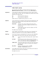
Cable Fault Location

To access the keys for setting up a cable fault location measurement, press 

MEASURE

Cable Fault Location

, and then the front panel 

Meas Setup

 key.

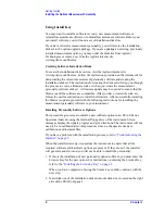
Avg Number 

Used to specify the number of data acquisitions that will be averaged. After the 
specified number of average counts, the averaging mode (terminal control) setting 
determines the averaging action. 

On


Sets measurement averaging on.

Off


Sets measurement averaging off.

Default values are 10 and Off, and range values are 1 to 1000.

Avg Mode 

Used to select the type of termination control used for the averaging function. This 
determines the averaging action after the specified number of data acquisitions 
(average count) is reached.

Exponential


After the average count is reached, each successive data 
acquisition is exponentially weighted and combined with the 
existing average.

Repeat


After reaching the average count, the averaging is reset and a 
new average is started.

The default value is exponential.

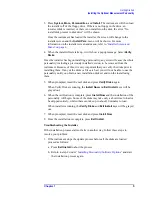
Calibrate

Used to calibrate the spectrum analyzer, removing any errors introduced by the 
cabling and components of the test setup before making the measurement.

Cable Type

Used to select the type of cable being tested. Provides access to the Cable Editor 
form, displaying a table listing relevant cable types, plus the following keys:

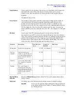
Cable


Used to select an entry in the cable type table. Accepts numeric 
values. 

Vel Factor 


The velocity factor for the cable type selected. The field’s 
numeric value represents a proportion of the speed of light. The 
value can be edited and saved using the 

Store Table

 key. 

Cable Loss/m


The amount of signal lost per meter for the cable type selected, 
expressed in dB. The value can be edited and saved using the 

Store Table

 key.

Store Table


Used to save any changes made to the 

Cable

Vel Factor

 or 

Cable Loss/m

 parameters. 

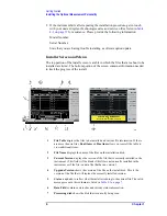
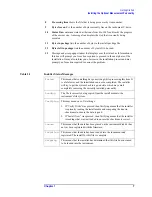
Start Distance

Used to define the start position of the range over which faults will be measured. 
This allows the user to zoom in on certain faults. 

The default value is 0 m.

Summary of Contents for ESA-E Series

Page 1: ... Technologies ESA E Series Spectrum Analyzers Cable Fault Measurement Personality Option 225 Manufacturing Part Number E4401 90312 Printed in USA May 2001 Supersedes E4401 90226 Copyright 2000 2001 Agilent Technologies Inc ...

Page 2: ...prepay shipping charges to Agilent Technologies and Agilent Technologies shall pay shipping charges to return the product to Buyer However Buyer shall pay all shipping charges duties and taxes for products returned to Agilent Technologies from another country Agilent Technologies warrants that its software and firmware designated by Agilent Technologies for use with an instrument will execute its ...

Page 3: ... a hazard It calls attention to a procedure that if not correctly performed or adhered to could result in damage to or destruction of the instrument Do not proceed beyond a caution sign until the indicated conditions are fully understood and met WARNING This is a Safety Class 1 Product provided with a protective earth ground incorporated in the power cord The mains plug shall be inserted only in a...

Page 4: ...iv ...

Page 5: ...s 11 Cable Fault Location 12 3 Making Measurements Chapter Contents 16 Making Cable Fault Measurements 17 Purpose 17 Calibrating the System 17 Reading the Cable Fault Location Measurement 21 Making Return Loss Measurements 22 Purpose 22 Making the measurement 22 Example 24 Making Loss Gain Measurements 29 Purpose 29 Making the measurement 29 Example 31 4 If You Have a Problem What to do Next 34 Be...

Page 6: ...vi Contents ...

Page 7: ...1 1 Getting Started This chapter describes the process for installing the personality ...

Page 8: ...u will want to keep a copy of your license key number in a secure location Please enter your license key numbers in the box provided below for future reference If you should lose your license key number get in touch with your local Agilent Technologies service or sales office for assistance For the location of these offices refer to Table 4 1 on page 37 You will need to use a license key number on...

Page 9: ... Spectrum Analyzers User s Guide 2 Use the alpha editor to enter the three letter designation for the software option that you wish to install in the instrument 3 Press Return when finished 4 Press License Key When you press License Key the alpha editor will be activated For instructions on using the alpha editor refer to the ESA Spectrum Analyzers User s Guide 5 Use the alpha editor to enter the ...

Page 10: ...r you have created the disk set follow the on line instructions to install the firmware After successfully installing the firmware update proceed with the following instructions for installing the measurement personalty software in your instrument Installing Personality Software Options This procedure gives steps to install a new software option in an ESA E Series Spectrum Analyzer using the inter...

Page 11: ...ng them If any of the disks or files are bad you will not be able to use the personality until you obtain a new installation disk set and run the install using them 5 When prompted insert the next disk and press Verify Disks again When Verify Disks is running the Install Now and Exit Install keys will be grayed out 6 When the verification is complete press Install Now and the installation of the p...

Page 12: ...installed and various file information If there are more then six files Next Item and Prev Item allow you to scroll the table to view additional items 2 File Name displays the name of the files on the installation disk 3 Current Version displays the version of the file that is currently installed in the instrument This field will be blank if this file is not currently installed in the instrument o...

Page 13: ... Failed This means that something has gone wrong while processing this item It is a fatal error and the installation can not be completed The installer will try to get the system back to a good state which may entail completely removing the currently installed personality Loading The file is currently being copied from the install media to the instrument s file system Verifying This may mean one o...

Page 14: ...8 Chapter1 Getting Started Installing the Optional Measurement Personality ...

Page 15: ...9 2 Menu Maps and Key Descriptions This chapter provides a visual representation of the front panel keys and their associated menu keys ...

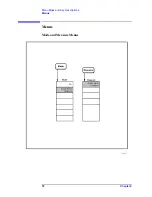
Page 16: ...10 Chapter2 Menu Maps and Key Descriptions Menus Menus Mode and Measure Menus ...

Page 17: ...Chapter 2 11 Menu Maps and Key Descriptions Menus Measurement Setup Menus Cable Fault Measurement Setup Menu ...

Page 18: ...hing the average count the averaging is reset and a new average is started The default value is exponential Calibrate Used to calibrate the spectrum analyzer removing any errors introduced by the cabling and components of the test setup before making the measurement Cable Type Used to select the type of cable being tested Provides access to the Cable Editor form displaying a table listing relevant...

Page 19: ...e trace To get the best possible results from the FFT it is important to apply the most suitable windowing function to the frequency trace before performing the FFT Possible values are Rectangular Flat Top Gaussian and Hanning The default value is Flat Top The following table describes these values Restore Meas Defaults Restores all Meas Setup parameter values for the current measurement to their ...

Page 20: ...evel of the internal source The default output level is 10 dBm Span Changes the frequency span used when acquiring the trace data prior to the FFT This in conjunction with Trace Points and Velocity Factor has a direct effect on the maximum distance that can be measured and the subsequent span resolution Span is provided for use in conjunction with Center Freq under FREQUENCY when measuring DUTs th...

Page 21: ...15 3 Making Measurements ...

Page 22: ...re described Cable fault location performed in cable fault location mode Return loss VSWR performed in SA mode Loss gain Transmit band low noise amplifier LNA gain and flatness receive band combiner loss and flatness performed in SA mode The return loss VSWR and loss gain measurements are not one button measurements All steps required to run them are fully detailed in this chapter ...

Page 23: ...e System For the following procedure use the appropriate 50 ohm or 75 ohm cables and accessories listed in Table 3 1 A return loss measurement requires the use of a power divider 1 Enter cable fault location mode and access the measurement a Press the Mode front panel key b Press the Cable Fault Location menu key c Connect the equipment as prompted by the dialog box and illustrated in Figure 3 1 T...

Page 24: ... appropriate cable type a Press the Cable Type menu key and observe the Cable Type Selection Screen as shown in Figure 3 2 b Page through available cable types using the Tab RPG or Step keys c Press the Select menu key to select the appropriate cable type d If you don t see your particular cable type listed you can modify one of the Custom cables at the end of the cable type list You will need to ...

Page 25: ...u key b Enter the appropriate value using the numeric key pad NOTE The above steps may cause the trace points parameter to be changed To prevent this from happening change this parameter to manual before attempting steps 2 through 4 If you choose to override this parameter the resultant trace may appear discontinuous 5 Calibrate the spectrum analyzer Calibration removes any errors introduced by th...

Page 26: ...n d Press Continue Your setup is now calibrated Connect a DUT device under test e Press Continue Figure 3 3 Cable Fault Location Measurement Setup 50 ohm only The 6 dB attenuators may be used to improve impedance matching 75 ohm only NOTE The distance to fault accessory kit Option B7K has all the 50 ohm accessories required to make these measurements Table 3 1 on page 17 lists the cables and acces...

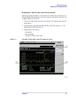
Page 27: ...o move the marker to the fault s of interest An example is shown in Figure 3 4 1 Connect the cable under test to the power divider The measurement will start automatically 2 Using the rotary pulse generator RPG knob position the marker 1 to the fault of interest Refer to Figure 3 4 3 Interpretation of the display Marker 1 Resolution 2 Distance to fault in meters 3 Figure 3 4 Example Cable Fault Lo...

Page 28: ...nitored and preventive action taken when required Making the measurement A return loss measurement requires the use of a signal separation device such as a directional coupler or bridge in addition to the device being tested for return loss The spectrum analyzer must be in spectrum analyzer mode for this measurement Procedure For the following procedure use the appropriate 50 ohm or 75 ohm cables ...

Page 29: ...panel key b Press the Amplitude menu key so that the tracking generator is turned on c Set an amplitude level appropriate for the device under test The default value 10 dBm 0 dBm may be used for systems with higher loss 3 Adjust the spectrum analyzer control settings for example frequency resolution bandwidth sweep time and input attenuation as appropriate for the signal separation device and devi...

Page 30: ...g SR SA menu key until SR is underlined 2 Establish a 0 dB reference trace for normalizing the measured data Normalization removes any frequency response errors introduced by the components of the test setup before making the measurement It is performed by removing the device to be tested and measuring a short or open As neither can dissipate the energy of the incident signal 100 reflection takes ...

Page 31: ... 75 ohm only NOTE The coaxial load shown in Figure 3 6 must be used if the DUT is a two port device 3 Make the measurement a Reconnect the device in place of the short open b Read the measurement and save it if required The return loss of the device is displayed on the screen Use the marker to evaluate the result and save the trace if required c An example is shown in Figure 3 7 ...

Page 32: ...26 Chapter 3 Making Measurements Making Return Loss Measurements Figure 3 7 Example Return Loss Measurement for a Bandpass Filter ...

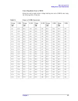
Page 33: ...30 0 1 07 40 0 1 02 11 0 1 78 15 0 1 43 20 5 1 21 30 5 1 06 40 5 1 02 11 2 1 76 15 2 1 42 21 0 1 20 31 0 1 06 41 0 1 02 11 4 1 74 15 4 1 41 21 5 1 18 31 5 1 05 41 5 1 02 11 6 1 71 15 6 1 40 22 0 1 17 32 0 1 05 42 0 1 02 11 8 1 69 15 8 1 39 22 5 1 16 32 5 1 05 42 5 1 02 12 0 1 67 16 0 1 38 23 0 1 15 33 0 1 05 43 0 1 01 12 2 1 65 16 2 1 37 23 5 1 14 33 5 1 04 43 5 1 01 12 4 1 63 16 4 1 36 24 0 1 13 ...

Page 34: ...Where RL is the measured return loss value VSWR is sometimes stated as a ratio For example 1 2 1 one point two to one VSWR The first number is the VSWR value taken from the table or calculated using the formula The second number is always 1 VSWR 1 10 RL 20 1 10 RL 20 ...

Page 35: ...omparing the result to the expected value A gain measurement can be used to test the performance of an amplifier A lower than expected gain measurement could indicate a fault with the amplifier Making the measurement The spectrum analyzer must be in spectrum analyzer mode for this measurement For the following procedure use the appropriate 50 ohm or 75 ohm cables and accessories listed in Table 3 ...

Page 36: ...r control settings for example frequency resolution bandwidth sweep time and input attenuation as appropriate for the device being tested 4 Establish a 0 dB reference trace for normalizing the measured data a Remove the device from the measurement path b Press the View Trace front panel key c Press the More menu key d Press the Normalize menu key Store Ref 1 3 and normalize On 5 Make the measureme...

Page 37: ...st slow it down until no changes in amplitude occur on the trace 2 Establish a 0 dB reference trace for normalizing the measured data Normalization removes any frequency response errors introduced by the components of the test setup before making the measurement It is performed by removing the device and measuring a thru from the source directly to the receiver This establishes a 0 dB reference tr...

Page 38: ... the tracking generator to the BPF input and the BPF output to the spectrum analyzer b Read the measurement and save it if required Use the marker to evaluate the result and save the trace if required c An example is shown in Figure 3 9 Figure 3 9 Example Loss Gain Measurement for a Bandpass Filter ...

Page 39: ...33 4 If You Have a Problem This chapter includes information on how to check for a problem with your ESA spectrum analyzer and how to return it for service ...

Page 40: ...lem 1 Refer to the user documentation to verify operation of the spectrum analyzer 2 If the problem is a hardware problem you have two options a Repair it yourself or b Return the analyzer to Agilent Technologies for repair If the analyzer is still under warranty or is covered by an Agilent Technologies maintenance contract it will be repaired under the terms of the warranty or plan the warranty i...

Page 41: ...is still under warranty or is covered by an Agilent Technologies maintenance contract it will be repaired under the terms of the warranty or plan the warranty is at the front of this manual If the analyzer is no longer under warranty or is not covered by an Agilent Technologies maintenance plan Agilent Technologies will notify you of the cost of the repair after examining the instrument See Contac...

Page 42: ...and service offices around the world to provide you with complete support for your analyzer To obtain servicing information or to order replacement parts get in touch with the nearest Agilent Technologies sales and service office listed in Table 4 1 In any correspondence or telephone conversations refer to your analyzer by its product number full serial number and firmware revision Press System Mo...

Page 43: ...a tel 305 269 7500 fax 305 269 7599 Australia tel 1 800 629 485 fax 61 3 9210 5947 Asia Call Center Numbers Country Phone Number Fax Number Singapore 1 800 375 8100 65 836 0252 Malaysia 1 800 828 848 1 800 801664 Philippines 632 8426802 1 800 16510170 PLDT Subscriber Only 632 8426809 1 800 16510288 PLDT Subscriber Only Thailand 088 226 008 outside Bangkok 662 661 3999 within Bangkok 66 1 661 3714 ...

Page 44: ...38 Chapter4 If You Have a Problem Before You Call Agilent Technologies ...

Page 45: ...surement personalities 2 internal source power level 14 J Japan 37 L Latin America 37 license key 3 how to record 2 requirements 2 limitation on sweep speed 31 loss gain measurement 29 M Malaysia 37 max range 12 maximum distance 14 meas setup cable fault location 12 measurement cable fault location 17 loss gain 29 return loss 22 menu map mode 10 menu maps 9 mode menu map 10 N New Zealand 37 O obta...

Page 46: ...Index 2 Index ...

Reviews: