30
Chapter 3
Making Measurements
Making Loss/Gain Measurements
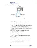
Figure 3-8
Loss/Gain Measurement Setup
* 50 ohm only. The 6 dB attenuators may be used to improve impedance matching.
2. Turn on the tracking generator.
a. Press the
Source
front panel key.
b. Press the
Amplitude
menu key so that the tracking generator is turned on.
c. Set an amplitude level appropriate for the device under test.
3. Adjust the spectrum analyzer control settings (for example frequency,
resolution bandwidth, sweep time and input attenuation) as appropriate for the
device being tested.
4. Establish a 0 dB reference trace for normalizing the measured data.
a. Remove the device from the measurement path.
b. Press the
View/Trace
front panel key.
c. Press the
More
menu key.
d. Press the
Normalize
menu key,
Store Ref (1 - 3)
and normalize
On
.
5. Make the measurement.
a. Reconnect the device.
b. Reconnect the tracking generator RF output to the device input and the
device output to the spectrum analyzer input as shown in
c. Read the measurement and save it if required.
Summary of Contents for ESA-E Series
Page 4: ...iv ...
Page 6: ...vi Contents ...
Page 7: ...1 1 Getting Started This chapter describes the process for installing the personality ...
Page 14: ...8 Chapter1 Getting Started Installing the Optional Measurement Personality ...
Page 16: ...10 Chapter2 Menu Maps and Key Descriptions Menus Menus Mode and Measure Menus ...
Page 21: ...15 3 Making Measurements ...
Page 44: ...38 Chapter4 If You Have a Problem Before You Call Agilent Technologies ...
Page 46: ...Index 2 Index ...


