background image

70

Chapter 1


Introduction to Programming X-Series Applications

STATus Subsystem (Remote Only Commands)

Summary of Contents for EXA N9010A

Page 1: ...lent Technologies Agilent X Series Signal Analyzer X Series Programmer s Guide This manual provides documentation for the following X Series Analyzers MXA Signal Analyzer N9020A EXA Signal Analyzer N9010A ...

Page 2: ...t prime contract or subcontract Software is delivered and licensed as Commercial computer soft ware as defined in DFAR 252 227 7014 June 1995 or as a commercial item as defined in FAR 2 101 a or as Restricted computer software as defined in FAR 52 227 19 June 1987 or any equivalent agency regulation or contract clause Use duplication or disclosure of Software is subject to Agilent Technologies sta...

Page 3: ...shall pay shipping charges to return the product to Buyer However Buyer shall pay all shipping charges duties and taxes for products returned to Agilent Technologies from another country Where to Find the Latest Information Documentation is updated periodically For the latest information about this analyzer including firmware upgrades application information and product information see the followi...

Page 4: ......

Page 5: ...ands 73 Putting Multiple Commands on the Same Line 76 Improving Measurement Speed 78 Turn off the display updates 78 Use binary data format instead of ASCII 78 Minimize the number of GPIB transactions 79 Consider using USB or LAN instead of GPIB 80 Minimize DUT instrument setup changes 80 Avoid unnecessary use of RST 80 Avoid automatic attenuator setting 80 Avoid using RFBurst trigger for single b...

Page 6: ...and Executing a List Sweep Measurement 95 Synchronizing a List Sweep Measurement Between an MXA and an MXG 96 For More Information 104 4 Programming Examples X Series Spectrum Analyzer Mode Programing Examples 108 89601X VXA Signal Analyzer Programming Examples 110 5 Installing Application Software Installing Application Software 114 Viewing a License Key 114 Obtaining and Installing a License Key...

Page 7: ...o Programming X Series Applications This chapter provides overall information regarding programming Agilent X Series Signal Analyzers with SCPI and the how to use the programming documentation provided with your product ...

Page 8: ...stem on the Additional Documentation page and is also available online here http cp literature agilent com litweb pdf N9020 90074 pdf The Getting Started Guide has valuable sections related to programming including Configuring instrument LAN Hostname IP Address and Gateway Address Using the Windows XP Remote Desktop to connect to the instrument remotely Using the Embedded Web Server Telnet connect...

Page 9: ...rument Software Architecture VISA library and shows how to use it to develop I O applications and instrument drivers on Windows PCs Available online here http cp literature agilent com litweb pdf 5989 6135EN pdf This document is also provided on the Documentation CD ROM and in the instrument here C Program Files Agilent SignalAnalysis Infrastructure Help otherdocs ...

Page 10: ...ed Help Metafile CHM is also provided on the Documentation CD ROM for access locally on your PC for reference In Microsoft Windows use Windows Explorer to navigate to the mode_name chm file on the CD ROM and double click the file to launch Help Help System Features Especially Useful for Programmers Help System Contents Pane The following programming specific features described below are shown in t...

Page 11: ...ted by front panel key groups as marked on the front panel For example Marker Functions contains all the Marker related hard keys Help Topics Included in each Help topic are Definitions for the current active function or Key SCPI Command parameters including limits presets variables and queries Associated Remote Only commands if used Figure 1 2 Example Help Topic FFT Window ...

Page 12: ...plication Each listing shown is a link to the specific Help Topic that contains the command or query See a partial example of a List of Commands in Figure 1 3 on page 12 Figure 1 3 Example List of Commands NOTE You can query the analyzer for all supported SCPI commands in the current mode by sending the SYST HELP HEAD query For details on how to query the instrument see Communicating SCPI Using Te...

Page 13: ...dress of the analyzer NOTE In addition to the procedure described below you can open a Telnet connection with the analyzer using an internet connection to the Embedded Web Server This procedure is described in the Getting Started guide To initiate a Telnet session and communicate SCPI using the LAN connection to the analyzer Step 1 Obtain the IP address of the analyzer If you don t know it a good ...

Page 14: ...r Telnet socket is On Press System I O Config SCPI LAN and make sure SCPI Telnet Port 5023 is toggled to On Step 3 Test your connection over the LAN On your PC using Microsoft Windows in the Taskbar select Start Run and enter cmd to open a DOS session Enter the DOS command ping a single space and the IP address of the analyzer and press Enter and the results should resemble the window shown below ...

Page 15: ...P address 5023 A Telnet window will open with a Welcome answerback from the analyzer Host Name and the command prompt will be shown as SCPI You can enter any valid SCPI command at the prompt and receive responses to queries sent NOTE You can query the analyzer for all supported SCPI commands in the current mode by sending the SYST HELP HEAD query ...

Page 16: ...e overall measurement FETch and READ are queries You can optimize your measurements by creating programs which use MEASure and CONFigure a minimum number of times and concentrating on repeating READ INITiate and FETCh commands For more information on optimizing your measurements see Improving Measurement Speed on page 78 The following graphic illustrates the interactions between the Measurement fa...

Page 17: ...e is set to a value other than 1 the selected trace data results will be returned See each command for details of what types of scalar results or trace data results are available ASCII is the default format for the data output The binary data formats should be used for handling large blocks of data since they are smaller and faster than the ASCII format Refer to the FORMat DATA command for more in...

Page 18: ...elected data from the most recent measurement into the output buffer Use FETCh if you have already made a good measurement and you want to return several types of data different n values for example both scalars and trace data from a single measurement FETCh saves you the time of re making the measurement You can only FETCh results from the measurement that is currently active it will not change t...

Page 19: ...er events for one full trigger cycle It also holds off additional commands on GPIB until the acquisition is complete READ Commands READ measurement n Does not preset the measurement to the factory default settings For example if you have previously initiated the ACP measurement and you send READ ACP it will initiate a new measurement using the same instrument settings Initiates the measurement and...

Page 20: ...ting specified by the FORMat BORDer and FORMat DATA commands and can return real or ASCII data See the format command descriptions under Input Output in the Analyzer Setup section Calculate Compress Trace Data Query Returns compressed data for the currently selected measurement and sub opcode n n any valid sub opcode for that measurement See the MEASure measurement command description of your spec...

Page 21: ...S RMSC SAMP SDEV and PPH return one data value for each specified region or length of trace data for as many regions as possible until you run out of trace data using roffset to specify regions Or they return the number of regions you specify using rlimit ignoring any data beyond that MINimum returns the minimum data point x y pair for the specified region s of Remote Command CALCulate DATA n COMP...

Page 22: ... presence of noise The mean of the power expressed in dB is useful in power measurements such as Channel Power To achieve the mean of the power use the RMS option Equation 1 Mean Value of Data Points for Specified Region s where Xi is a data point value and n is the number of data points in the specified region s Equation 2 Mean Value of I Q Data Pairs for Specified Region s where Xi is the magnit...

Page 23: ...ber and n is the number of I Q pairs in the specified region s Once you have the rms value for a region of trace data linear or I Q you may want to calculate the mean power You must convert this rms value peak volts to power in dBm 10 x log 10 x rms value 2 SAMPle returns the first data value x y pair for the specified region s of trace data For I Q trace data the first I Q pair is returned SDEVia...

Page 24: ...ecified by data point in PPHase The rms power of the specified region may be expressed as Power 10 x log 10 x RMS I Q value 10 The RMS I Q value peak volts is where Xi is the complex value representation of an I Q pair Xi its conjugate complex number and n is the number of I Q pairs in the specified region The arithmetic mean phase of the specified region may be expressed as where Yi is the unwrap...

Page 25: ...for frequency domain traces It defines how much data will be compressed into one value This parameter has a default value equal to the current trace length roffset repeat offset is an optional real number It is in seconds for time domain traces and is a dimensionless index 0 to Npoints 1 for frequency domain traces It defines the beginning of the next field of trace elements to be compressed This ...

Page 26: ...h real and complex traces can be searched but complex traces are converted to magnitude in dBm In many measurements the sub opcode n 0 is the raw trace data which cannot be searched for peaks And Sub opcode n 1 is often calculated results values which also cannot be searched for peaks This command uses the data setting specified by the FORMat BORDer and FORMat DATA commands and can return real or ...

Page 27: ...criterion for this command provide a substantially low threshold value such as 200 dBm Also note that the threshold value used in this command is independent of and has no effect on the threshold value stored under the Peak Criteria menu excursion is the minimum amplitude variation rise and fall required for a signal to be identified as peak Note that the excursion value is required and is always ...

Page 28: ...ether a peak should be reported Remote Command FORMat TRACe DATA ASCii INTeger 32 REAL 32 REAL 64 FORMat TRACe DATA Dependencies Couplings Sending a data format spec with an invalid number for example INT 48 generates no error The analyzer simply uses the default 8 for ASCii 32 for INTeger 32 for REAL Sending data to the analyzer which does not conform to the current FORMat specified results in an...

Page 29: ...der Remote Command Only This command selects the binary data byte order for data transfer and other queries It controls whether binary data is transferred in normal or swapped mode This command affects only the byte order for setting and querying trace data for the TRACe DATA TRACe DATA CALCulate DATA n and FETCh SANalyzer n commands and queries By definition any command that says it uses FORMat D...

Page 30: ...ans Filter Trans Filter Event Enable Reg Event Register Condition Register Trans Filter Trans Filter Reserved Reserved Reserved Reserved Reserved 50 MHz Input Pwr too High for Cal Reserved Unused Reserved Preselector Overload Unused Unused Unused Unused Unused Always Zero 0 STATus QUEStionable Unused Unused Unused Unused Reserved Unused Unused Unused Unused Unused Unused Unused Unused Unused Unuse...

Page 31: ...ATus QUEStionable INTegrity UNCalibrated for Base Analyzer STATus QUEStionable INTegrity SIGNal for Base Analyzer Unused Data Uncalibrated Sum 0 1 2 3 4 5 6 7 8 9 10 11 12 13 14 15 0 1 2 3 4 5 6 7 8 9 10 11 12 13 14 15 0 1 2 3 4 5 6 7 8 9 10 11 12 13 14 15 Carrier s incorrect or missing Timing Error Burst Not Found Reserved Unused Reserved Sync Error Demod Error Signal too Noisy Unused Unused Unus...

Page 32: ...ed by this register set There is no latching or buffering for a condition register Positive Transition Register This filter register controls which signals will set a bit in the event register when the signal makes a low to high transition when the condition bit changes from 0 to 1 Negative Transition Register This filter register controls which signals will set a bit in the event register when th...

Page 33: ... the service request enable register and the event status enable register at power on SRE SRE service request enable sets and queries the value of the service request enable register STB status byte queries the value of the status byte register without erasing its contents How to Use the Status Registers A program often needs to be able to detect and manage error conditions or changes in instrumen...

Page 34: ...it You can enable a particular bit s using the event enable register The instrument will then monitor that particular condition s If the bit becomes true 0 to 1 transition in the event register it stays set until the event register is cleared Querying the event register allows you to detect that this condition occurred even if the condition no longer exists The event register can only be cleared b...

Page 35: ...bit 10 events instead of the default monitoring all the bits in the register The register default is for positive transition events 0 to 1 transition That is when an auto trigger timeout occurs If instead you wanted to know when the Auto trigger timeout condition is cleared then you would set the STAT QUES INT PTR 0 and the STAT QUES INT NTR 32767 4 So now the only output from the Status Questiona...

Page 36: ... a summary bit in the status byte to change from 0 to 1 the instrument can initiate the service request SRQ process However the process is only initiated if both of the following conditions are true The corresponding bit of the service request enable register is also set to 1 The instrument does not have a service request pending A service request is considered to be pending between the time the i...

Page 37: ...r System The hardware status registers are combined to form the instrument status system Specific status bits are assigned to monitor various aspects of the instrument operation and status See the diagram of the status system above for information about the bit assignments and status register interconnections The Status Byte Register The RQS bit is read and reset by a serial poll The same bit posi...

Page 38: ...is not empty which means that it contains at least one error message 3 A 1 in this bit position indicates that the data questionable summary bit has been set The data questionable event register can then be read to determine the specific condition that caused this bit to be set 4 A 1 in this bit position indicates that the instrument has data ready in the output queue There are no lower status gro...

Page 39: ...le plus the decimal value of bit 6 For example assume that you want to enable bit 7 so that whenever the standard operation status register summary bit is set to 1 it will trigger a service request Send the command SRE 192 because 192 128 64 You must always add 64 the numeric value of RQS bit 6 to your numeric sum when you enable any bits for a service request The command SRE returns the decimal v...

Page 40: ...hapter1 Introduction to Programming X Series Applications STATus Subsystem Remote Only Commands Standard Event Status Register The standard event status register contains the following bits Bit Description ...

Page 41: ... to 1 send the command ESE 192 128 64 The command ESE returns the decimal value of the sum of the bits previously enabled with the ESE integer command The standard event status enable register presets to zeros 0 0 A 1 in this bit position indicates that all pending operations were completed following execution of the OPC command 1 This bit is for GPIB handshaking to request control Currently it is...

Page 42: ...e has happened to it It is looking for anything that might cause an error or a bad measurement like a hardware problem an out of calibration situation or a unusual Bit Condition Operation 0 Calibrating The instrument is busy executing its Align Now process 3 Sweeping The instrument is busy taking a sweep 4 Measuring The instrument is busy making a measurement Measurements often require multiple sw...

Page 43: ...gister is continuously updated and reflects the current conditions Operation Enable This command determines which bits in the Operation Event register will set the Operation Status Summary bit bit 7 in the Status Byte Register The variable integer is the sum of the decimal values of the bits you want to enable Bit Condition Operation 3 Power summary The instrument hardware has detected a power unl...

Page 44: ...ueried Once queried the register is cleared Operation Negative Transition This command determines which bits in the Operation Condition register will set the corresponding bit in the Operation Event register when the condition register bit has a negative transition 1 to 0 The variable integer is the sum of the decimal values of the bits that you want to enable Mode All Remote Command STATus OPERat...

Page 45: ...ue IEEE 488 2 ESE and SRE Registers as described in IEEE Standard 488 2 1992 IEEE Standard Codes Formats Protocols and Common Commands for Use with ANSI IEEE Std 488 1 1987 New York NY 1992 Questionable Register Questionable Condition This query returns the decimal value of the sum of the bits in the Questionable Condition register The data in this register is continuously updated and reflects the...

Page 46: ...o hardware problem or measurement problem was detected by the analyzer Questionable Event Query This query returns the decimal value of the sum of the bits in the Questionable Event register The register requires that the associated PTR or NTR filters be set before a condition register bit can set a bit in the event register The data in this register is latched until it is queried Once queried the...

Page 47: ...u want to enable Questionable Calibration Register Questionable Calibration Condition This query returns the decimal value of the sum of the bits in the Questionable Calibration Condition register The data in this register is continuously updated and reflects the current conditions Mode All Remote Command STATus QUEStionable NTRansition 16 Temperature summary questionable cleared will be reported ...

Page 48: ...Once queried the register is cleared Questionable Calibration Negative Transition This command determines which bits in the Questionable Calibration Condition register will set the corresponding bit in the Questionable Calibration Event register when the condition register bit has a negative transition 1 to 0 The variable integer is the sum of the decimal values of the bits that Remote Command STA...

Page 49: ...n Skipped Condition This query returns the decimal value of the sum of the bits in the Questionable Calibration Skipped Condition register NOTE The data in this register is continuously updated and reflects the current conditions Mode All Remote Command STATus QUEStionable CALibration NTRansition integer STATus QUEStionable CALibration NTRansition Example STAT QUES CAL NTR 16384 Alignment is not r...

Page 50: ...t the associated PTR or NTR filters be set before a condition register bit can set a bit in the event register The data in this register is latched until it is queried Once queried the register is cleared Remote Command STATus QUEStionable CALibration SKIPped CONDition Example STAT QUES CAL SKIP COND Preset 0 SCPI Status Bits OPC Dependencies Sequential command Mode All Remote Command STATus QUESt...

Page 51: ...ition register bit has a positive transition 0 to 1 The variable integer is the sum of the decimal values of the bits that you want to enable Questionable Calibration Extended Failure Register Questionable Calibration Extended Failure Condition This query returns the decimal value of the sum of the bits in the Questionable Calibration Extended Failure Condition register Mode All Remote Command STA...

Page 52: ... returns the decimal value of the sum of the bits in the Questionable Calibration Extended Failure Event register NOTE The register requires that the associated PTR or NTR filters be set before a condition register bit can set a bit in the event register The data in this register is latched until it is queried Once queried the Mode All Remote Command STATus QUEStionable CALibration EXTended FAILur...

Page 53: ...in the Questionable Calibration Extended Failure Event register when the condition register bit has a positive transition 0 to 1 The variable integer is the sum of the decimal values of the bits that you want to enable Mode All Remote Command STATus QUEStionable CALibration EXTended FAILure EVENt Example STAT QUES CAL EXT FAIL Preset 0 SCPI Status Bits OPC Dependencies Sequential command Mode All ...

Page 54: ...ister will set bits in the Questionable Calibration Extended Needed Event register which also sets bit 14 of the Questionable Calibration Register The variable integer is the sum of the decimal values of the bits you want to enable Preset 32767 Min 0 Max 32767 SCPI Status Bits OPC Dependencies Sequential command Mode All Remote Command STATus QUEStionable CALibration EXTended NEEDed CONDition Exam...

Page 55: ...he Questionable Calibration Extended Needed Event register when the condition register bit has a negative transition 1 to 0 The variable integer is the sum of the decimal values of the bits that you want to enable Questionable Calibration Extended Needed Positive Transition This command determines which bits in the Questionable Calibration Extended Needed Condition register will set SCPI Status Bi...

Page 56: ...termines which bits in the Questionable Frequency Condition Register will set bits in the Questionable Frequency Event register which also sets the Frequency Summary bit bit 5 in the Questionable Register The variable integer is the sum of the decimal values of the bits you want to enable Mode All Remote Command STATus QUEStionable CALibration EXTended NEEDed PTRansition integer STATus QUEStionabl...

Page 57: ...it in the Questionable Frequency Event register when the condition register bit has a negative transition 1 to 0 The variable integer is the sum of the decimal values of the bits that you want to enable Example STAT QUES FREQ ENAB 2 Frequency Reference Unlocked is reported to the Frequency Summary of the Status Questionable register Preset 32767 Min 0 Max 32767 SCPI Status Bits OPC Dependencies Se...

Page 58: ...continuously updated and reflects the current conditions Questionable Integrity Enable This command determines which bits in the Questionable Integrity Condition Register will set bits in the Questionable Integrity Event register which also sets the Integrity Summary bit bit 9 in the Questionable Register The Max 32767 SCPI Status Bits OPC Dependencies Sequential command Mode All Remote Command ST...

Page 59: ...able Integrity Condition register will set the corresponding bit in the Questionable Integrity Event register when the condition register bit has a negative transition 1 to 0 The variable integer is the sum of the decimal values of the bits that you want to enable Mode All Remote Command STATus QUEStionable INTegrity ENABle integer STATus QUEStionable INTegrity ENABle Example STAT QUES INT ENAB 8 ...

Page 60: ...nable Integrity Signal Condition register NOTE The data in this register is continuously updated and reflects the current conditions Example STAT QUES INT NTR 8 Measurement regained calibration Summary will be reported to the Integrity Summary of the Status Questionable register Preset 0 Min 0 Max 32767 SCPI Status Bits OPC Dependencies Sequential command Mode All Remote Command STATus QUEStionabl...

Page 61: ...is register is latched until it is queried Once queried the register is cleared Questionable Integrity Signal Negative Transition This command determines which bits in the Questionable Integrity Signal Condition register will set the corresponding bit in the Questionable Integrity Signal Event register when the condition register bit has a negative transition 1 to 0 The variable integer is the sum...

Page 62: ...value of the sum of the bits in the Questionable Integrity Uncalibrated Condition register NOTE The data in this register is continuously updated and reflects the Mode All Remote Command STATus QUEStionable INTegrity SIGNal NTRansition integer STATus QUEStionable INTegrity SIGNal NTRansition Example STAT QUES INT SIGN NTR 4 Burst found will be reported to the Integrity Summary of the Status Questi...

Page 63: ...ity Uncalibrated Event register NOTE The register requires that the associated PTR or NTR filters be set before a condition register bit can set a bit in the event register The data in this register is latched until it is queried Once queried the register is cleared Mode All Remote Command STATus QUEStionable INTegrity UNCalibrated CONDition Example STAT QUES INT UNC COND Preset 0 SCPI Status Bits...

Page 64: ...ated Event register when the condition register bit has a positive transition 0 to 1 The variable integer is the sum of the decimal values of the bits that you want to enable Example STAT QUES INT UNC Preset 0 SCPI Status Bits OPC Dependencies Sequential command Mode All Remote Command STATus QUEStionable INTegrity UNCalibrated NTRansition integer STATus QUEStionable INTegrity UNCalibrated NTRansi...

Page 65: ...ues of the bits you want to enable Questionable Power Event Query This query returns the decimal value of the sum of the bits in the Questionable Power Event register NOTE he register requires that the associated PTR or NTR filters be set before a condition register bit can set a bit in the event register The data in SCPI Status Bits OPC Dependencies Sequential command Mode All Remote Command STAT...

Page 66: ...r Event register when the condition register bit has a positive transition 0 to 1 The variable integer is the sum of the decimal values of the bits that you want to enable Mode All Remote Command STATus QUEStionable POWer EVENt Example STAT QUES POW Preset 0 SCPI Status Bits OPC Dependencies Sequential command Mode All Remote Command STATus QUEStionable POWer NTRansition integer STATus QUEStionabl...

Page 67: ... Questionable Register The variable integer is the sum of the decimal values of the bits you want to enable Questionable Temperature Event Query This query returns the decimal value of the sum of the bits in the Questionable Temperature Event register Min 0 Max 32767 SCPI Status Bits OPC Dependencies Sequential command Mode All Remote Command STATus QUEStionable TEMPerature CONDition Example STAT ...

Page 68: ... you want to enable Questionable Temperature Positive Transition This command determines which bits in the Questionable Temperature Condition register will set the corresponding bit in the Questionable Temperature Event register when the condition register bit has a positive transition 0 to 1 The variable integer is the sum of the decimal values of the bits that you want to enable Mode All Remote ...

Page 69: ...Tus QUEStionable TEMPerature PTRansition integer STATus QUEStionable TEMPerature PTRansition Example STAT QUES TEMP PTR 1 Reference Oscillator Oven became cold will be reported to the Temperature Summary of the Status Questionable register Preset 32767 Min 0 Max 32767 SCPI Status Bits OPC Dependencies Sequential command ...

Page 70: ...70 Chapter1 Introduction to Programming X Series Applications STATus Subsystem Remote Only Commands ...

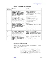
Page 71: ...ard Digital Interface for Programmable Instrumentation Topics covered in this chapter include Creating Valid Commands on page 72 Command Keywords and Syntax on page 71 Special Characters in Commands on page 73 Parameters in Commands on page 73 Putting Multiple Commands on the Same Line on page 76 Command Keywords and Syntax A typical command is made up of keywords set off by colons The keywords ar...

Page 72: ...mmand Syntax Sample Valid Commands SENSe BANDwidth RESolution freq The following sample commands are all identical They will all cause the same result Sense Band Res 1700 BANDWIDTH RESOLUTION 1 7e3 sens band 1 7KHZ SENS band 1 7E3Hz band 1 7kHz bandwidth RES 1 7e3Hz MEASure SPECtrum n MEAS SPEC Meas spec meas spec3 The number 3 in the last meas example causes it to return different results then th...

Page 73: ...d choice A vertical stroke between keywords indicates identical effects exist for both keywords The command functions the same for either keyword Only one of these keywords is used at a time Command SENSe BANDwidth BWIDth OFFSet Two identical commands are Ex1 SENSE BWIDTH OFFSET Ex2 SENSE BAND OFFSET keywords in square brackets are optional when composing the command These implied keywords will be...

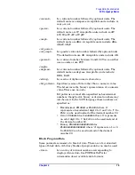
Page 74: ...t resets the parameter to its default value UP increments the parameter DOWN decrements the parameter MINimum sets the parameter to the smallest possible value MAXimum sets the parameter to the largest possible value The numeric value for the function s MINimum MAXimum or DEFault can be queried by adding the keyword to the command in its query form The keyword must be entered following the questio...

Page 75: ...aracters bit_pattern Specifies a series of bits rather than a numeric value The bit series is the binary representation of a numeric value There are no units Bit patterns are most often specified as hexadecimal numbers though octal binary or decimal numbers may also be used In the SCPI language these numbers are specified as Hexadecimal Hdddd or hdddd where d represents a hexadecimal digit 0 to 9 ...

Page 76: ...her 8 for real 64 or 4 for real 32 For this example if you re using real64 then there are 1540 points in the block Putting Multiple Commands on the Same Line Multiple commands can be written on the same line reducing your code space requirement To do this Commands must be separated with a semicolon If the commands are in different subsystems the key word for the new subsystem must be preceded by a...

Page 77: ...ut executing the FREQ command puts you back at the SENSE level You must specify POW to get to the MIX RANG command FREQ STAR 30MHz POW MIX RANG 20dBm FREQ STAR 30MHz POW MIX RANG 20dBm MIX and RANG require a colon to separate them POW ATT 40dB TRIG FREQ STAR 2 3GHz POW ATT 40dB FREQ STAR 2 3GHz FREQ STAR is in the SENSE subsystem not the TRIGGER subsystem POW ATT FREQ STAR POW ATT FREQ STAR POW an...

Page 78: ...lay slows down the measurement For remote testing since the computer is processing the data rather than a person there is no need to display the data on the analyzer screen Use binary data format instead of ASCII The ASCII data format is the instrument default since it is easier for people to understand and is required by SCPI for RST However data input output is faster using the binary formats FO...

Page 79: ... SCPI Language Basics section If you are making the same measurement multiple times with small changes in the measurement setup use the READ command It is faster then using INITiate and FETCh If you are changing the frequency and making a measurement repeatedly you can reduce transactions by sending the optional frequency parameter with your READ command for example READ meas freq These optional p...

Page 80: ...ameter changes as you step through the test Are you are using the measurements under the Meas key Remember that if you have already set your Meas Setup parameters for a measurement and you want to make another one of these measurements later use READ meas The MEASure meas command resets all the settings to the defaults while READ changes back to that measurement without changing the setup paramete...

Page 81: ... the trigger being done at the wrong level point generating incorrect data or it may not trigger at all Are you making a single burst measurement To get consistent triggering and good data for this type of measurement application you need to synchronize the triggering of the DUT with the analyzer You should use the analyzer s internal status system for this The first step in this process is to ini...

Page 82: ...with just one measurement instead of a separate measurement on each slot and 2 it can pre process and or decimate the data so that you only return the information that you need which minimizes data transfer to the computer For example let s say you want to do a power measurement for a GSM base station where you generate a repeating frame with 8 different power levels You can gather all the data wi...

Page 83: ...r with later firmware MEAN 25us 526us 579 6us 8 MEAN calculates the mean of the measurement points indicated 9 is how many points you want to discard before you look at the data This allows you to skip over any unsettled values at the beginning of the burst You can calculate this start offset by 25μs sampleInterval l 197 is the length of the data you want to use This would be the portion of the bu...

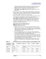
Page 84: ...engineers connecting instruments to computers who use Microsoft Windows based applications and application development environments http www adn tm agilent com The Agilent MXA website has many topics under the Technical Support tab including Application Notes http www agilent com find mxa 500 kHz Flat 4 1 6 μsec 15 329 360 575 300 kHz Gaussian 1 0 2667 μsec 90 1972 2163 1 300 kHz Gaussian 4 1 07 μ...

Page 85: ...he instrument menus and web pages do not imply LXI Class B compliance This product will apply for LXI Class B Compliance when the LXI Consortium has approved its specification changes and can provide certified testing IEEE 1588 The IEEE 1588 standard defines a Precision Time Protocol PTP for synchronizing various clocks connected by Ethernet This will give your measurement instrumentation a common...

Page 86: ...Ck PTP DOMain 0 Make sure this domain number matches the one entered in Task 3 Task Action Notes 1 Open Interactive LXI Start All Programs Agilent IO Libraries Suite Utilities Interactive LXI This operation should be performed on a PC connected to the same subnet as the MXA and MXG 2 Open the Timing menu Click on the tab labeled Timing 3 Choose an active domain Select the domain entered as the Act...

Page 87: ...ill apply for LXI Class B Compliance when the LXI Consortium has approved its specification changes and can provide certified testing Outputting LAN Events The MXA can be configured to send LXI Output LAN Events using either the front panel or SCPI by following the procedures below Instrument Event Description OperationComplete Indicates whether or not a measurement operation is underway For examp...

Page 88: ...s 4 Choose an LXI Output LAN Event Click on the event in the list that should appear on the wire You will see a list of event names Notice that the last 5 events are named after the instrument events above 5 Choose an instrument event source If LAN0 LAN7 were chosen in Task 4 click the softkey labeled Source then choose the desired instrument event from the menu If one of the last 5 events was cho...

Page 89: ... LAN7 Note that valid entries for the second parameter include the list of Instrument Events in Table 3 as well as the LXI Input LAN Events LAN0 LAN7 The instrument will echo received LXI Input LAN Events when used as a source 3 Enable the LXI Output LAN Event LXI EVENt LAN OUTPut ENABled LAN0 1 Turn the LAN0 LXI Output LAN Event on Note that the parameter should match the first parameter in Task ...

Page 90: ... an LXI Class B instrument by adding LAN Triggering and Time Synchronization to its LXI Class C compliance References to LXI Class B in the document and in the instrument menus and web pages do not imply LXI Class B compliance This product will apply for LXI Class B Compliance when the LXI Consortium has approved its specification Task Action Notes 1 Open Interactive LXI Start All Programs Agilent...

Page 91: ...mple a channel power measurement would select the trigger source using the SCPI command TRIGger CHP SOURce LAN 3 Enable a specific Trigger LAN Event TRIGger LXI LAN ENABled LAN0 1 The default state for LAN0 LAN7 is disabled The instrument will trigger upon the receipt of an enabled LAN event Note that this command does not include an additional measurement node This command will be identical for b...

Page 92: ...nt that should cause the instrument to trigger You will see a list of Trigger LAN Event names 4 Enable the Trigger LAN Event Click the Enabled soft key This is equivalent to Task 3 in the procedure Configuring an LXI Trigger Using SCPI on page 90 Note that Tasks 3 4 may be repeated for as many LAN Events as desired 5 Turn on continuous measurement mode Press the hard key labeled Cont Task Action N...

Page 93: ...ut LAN Events on page 90 This may be done assuming Configuring an LXI Trigger Using SCPI on page 90 or Configuring an LXI Trigger Using the Front Panel on page 92 are complete Task Action Notes 1 Place the instrument in the state to be recalled Various SCPI commands may be used This step is up to the user s discretion 2 Save the state MMEM STOR STATe c States myState state The path must exist and ...

Page 94: ...I Using the LXI Event Log The final piece to the LXI puzzle is the LXI Event Log The event log records all of the enabled LXI Event and Instrument Event activity and associates each action with an IEEE 1588 timestamp Instrument Events are enabled by default and will therefore appear in the log Since many instrument events occur during every sweep logging all of them may flood the event log They ma...

Page 95: ...causing it to source the first signal in its list We then start the MXA s list sweep The OperationComplete instrument event transitions low causing an OperationComplete output event to go out on the LAN with a falling edge The MXA takes a measurement at the first frequency in its list When the MXA has finished its measurement it moves on to the next entry in its list The WaitingForTrigger instrume...

Page 96: ...retrieve the list sweep measurement results from the MXA Synchronizing a List Sweep Measurement Between an MXA and an MXG Synchronizing Using Peer to Peer messages The following procedure allows you to Synchronize a List Sweep measurement between an MXA and an MXG using Peer to Peer messages Task Action Notes 1 Disable LXI Output LAN Events on the MXG LXI EVENt OUTPut LAN DISable ALL This command ...

Page 97: ...The MXG will put out signals at these powers and in this order 11 Turn off signal modulation OUTP MOD OFF This command is sent to the MXG 12 Turn signal output on OUTP ON This command is sent to the MXG 13 Configure the MXG s LXI Output LAN Event LXI EVENt OUTPut LAN DRIVe LAN0 NORMal LXI EVENt OUTPut LAN SLOPe LAN0 POS LXI EVENt OUTPut LAN SOURce LAN0 WaitingForTrigger These commands are sent to ...

Page 98: ...meter value should match the one used in Task 3 21 Choose the MXA s LXI domain LXI EVENt DOMain 0 This command is sent to the MXA The parameter value should match the one used in Task 4 22 Move the MXA into the list sweep measurement CONF LIST This command is sent to the MXA 23 Send the MXA a list of frequencies LIST FREQ 100 MHz 200 MHz 300 MHz 400 MHz 500 MHz This command is sent to the MXA Meas...

Page 99: ...rTrigger instrument event changes state 28 Enable the MXA s LXI LAN Event trigger TRIG LXI LAN ENABled LAN0 1 This command is sent to the MXA 29 Enable the MXA s LXI Output LAN Events LXI EVENt OUTPut LAN ENABled LAN1 1 LXI EVENt OUTPut LAN ENABled OperationComplete 1 These commands are sent to the MXA The LAN1 peer to peer message is now enabled The MXA will send an OperationComplete peer to peer...

Page 100: ...to the MXA This will cause the MXA to take a measurement at the first frequency in its list It will also begin waiting for the alarm to fire before moving on to the next measurement 32 Wait for the OperationComplete instrument event Detect the peer to peer traffic using Interactive LXI To programmatically listen for LXI peer to peer messages use the IOLibraries TMFramework LXI library When the MXA...

Page 101: ...e entered LIST TYPE LIST An arbitrary list will be used instead of range and step size arguments 9 Send the MXG a list of frequencies LIST FREQ 100 MHz 200 MHz 300 MHz 400 MHz 500 MHz This command is sent to the MXG The MXG will put out signals at these frequencies and in this order 10 Send the MXG a list of powers LIST POW 0 dBm 1 dBm 2 dBm 3 dBm 4 dBm This command is sent to the MXG The MXG will...

Page 102: ...ming variability 18 Put the MXA into SA mode INST SEL SA This command is sent to the MXA 19 Turn off continuous measurements INIT CONT OFF This command is sent to the MXA 20 Put the MXA into the list sweep measurement CONF LIST This command is sent to the MXA 21 Send the MXA a list of frequencies LIST FREQ 100 MHz 200 MHz 300 MHz 400 MHz 500 MHz This command is sent to the MXA 22 Configure the MXA...

Page 103: ... Determine master clock LXI CLOCk SYNC MASTer This query is sent to each instrument Whichever instrument returns 1 is the master clock 26 Query PTP time LXI CLOCk TIME SEConds This query is sent to the master It s response will be referred to as dblTimeSeconds 27 Calculate the measurement s start times startTime dblTimeSeconds 60 0 The measurement will start a minute after Task 26 was executed 28 ...

Page 104: ...ALARM0 5 TRIGger LXI ALARm TIME ALARM0 startTime 0 5 TRIGger LXI ALARM ENABled ALARM0 1 These commands are sent to the MXA The repeat parameter should match the number of frequencies in the list The first alarm will fire 0 5 seconds after the MXG s A new alarm will fire every second 30 Wait for the OperationComplete instrument event Detect the peer to peer traffic using Interactive LXI To programm...

Page 105: ... For More Information How to Use VXI and PXI in Your New LXI Test System AN 1465 23 Using Synthetic Instruments in Your Test System AN 1465 24 Migrating system software from GPIB to LAN LXI AN 1465 25 Modifying a GPIB System to Include LAN LXI AN 1465 26 ...

Page 106: ...106 Chapter3 Measurement Synchronization with LXI B For More Information ...

Page 107: ...easurement Toolkit You can now develop application programs that are portable across computer platforms and I O interfaces With IVI COM drivers you do not need to have in depth test instrument knowledge to develop sophisticated measurement software IVI COM drivers provide a compatible interface to all COM environments The IVI COM software drivers can be found at the URL http www agilent com find i...

Page 108: ...l other modes However they should work in all other modes except where exceptions are noted Programming using Visual Basic 6 Visual Basic NET and MS Excel Transfer Screen Images from your Spectrum Analyzer using Visual Basic 6 This example program stores the current screen image on the instrument flash memory as D PICTURE PNG It then transfers the image over GPIB or LAN and stores the image on you...

Page 109: ...are registers monitor various events and conditions in the instrument Details about the use of these commands and registers can be found in the manual help in the Utility Functions section on the STATus subsystem File name _SRQ C Relative Band Power Markers using C This example demonstrates how to set markers as Band Power Markers and obtain their band power relative to another specified marker Fi...

Page 110: ...ns 1001 trace points for the signal analyzer File name transfertrace vee 89601X VXA Signal Analyzer Programming Examples The following examples work with 89601X VXA Signal Analyzer Mode These examples use one of the following programming languages Visual Basic 6 Visual Studio 2003 NET and Agilent VEE Pro These examples are available in either the progexamples directory on the Agilent Technologies ...

Page 111: ...ads the trace data EVM and demodulated bits File name VXA DigDemodDemo vbs Programming using Agilent VEE Pro Setting up a VSA Measurement on your 89601X VXA using VEE This example program Sets up the VSA Mode Sets the Vector Measurement Configures the Vector Measurement Starts the Vector Measurement Reads the trace data in Real 32 Real 64 and ASCII data format File name VXA MeasDemo vee Setting up...

Page 112: ...Measurement Configures the Vector Measurement Starts the Vector Measurement Reads the trace data in Real 64 data format File name VXA MeasDemo sln Setting up a Digital Demod Measurement on your 89601X VXA using Visual Basic 6 This example program Sets up the VSA Mode Sets the Digital Demod Measurement Configures the Digital Demod Measurement Starts the Digital Measurement Reads the trace data EVM ...

Page 113: ...ter 5 113 Installing Application Software 5 Installing Application Software The following section details installing software in your analyzer and provides information on viewing and Installing License Keys ...

Page 114: ... Key for every measurement application purchased The license key is a hexadecimal string that is specific to your measurement application instrument model number and serial number It enables you to install or reactivate that particular application Press System Show System to display which measurement applications are currently licensed in your analyzer Go to the following location to view the lice...

Page 115: ...re applications were loaded at the time of original instrument manufacture It is a good idea to regularly update your software with the latest available version This assures that you get any improvements and expanded functionality that is available Because the software was loaded at the initial purchase there may be additional measurement applications that are now available If the application you ...

Reviews: