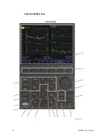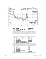
CAT (Cable and Antenna Test) Mode
23
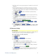
Then choose from the following:
o
Start
and
Stop
frequencies - beginning and end of the sweep.
o
Center
and
Span
frequencies – the center frequency and span of
frequencies (half on either side of center).
Follow each setting by entering a value using the numeric keypad,
▲|▼
arrows, or the rotary knob.
o
After using the keypad, select a multiplier key. Learn about multiplier
abbreviations on page 19.
o
After using the
▲|▼
arrows or the rotary knob, press
Enter
. The amount of
frequency increment is based on the current span and can NOT be changed
in CAT Mode.
Scale Settings
Adjust the Y-axis scale to see the relevant portions of the data trace. The Y-axis is
divided into 10 graticules.
This setting can be changed at any time without affecting calibration accuracy.
How to set Scale
Press
Scale / Amptd
.
Then choose from the following three methods:
1.
Autoscale
Automatically adjusts the Y-axis to comfortably fit the Min and
Max amplitude of the trace on the screen.
2. Set Scale, Reference Level, and Reference Position:
o
Scale
Manually enter a
scale per division
to view specific areas of the trace.
o
Ref Level
Manually set the value of the reference line. Enter a negative
value by pressing
Run/Hold (+/-)
either before or after typing a value.
o
Ref Position
Manually set the position of the reference line. Values must be
between
0
(TOP line) and
10
(BOTTOM line)
3. Set Top and Bottom graticule values. The scale per division is calculated.
o
Top
to set the value of the Top graticule.
o
Bottom
to set the value of the Bottom graticule.
o
Enter a negative value by pressing
Run/Hold (+/-)
either before or after
typing a value.
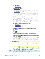
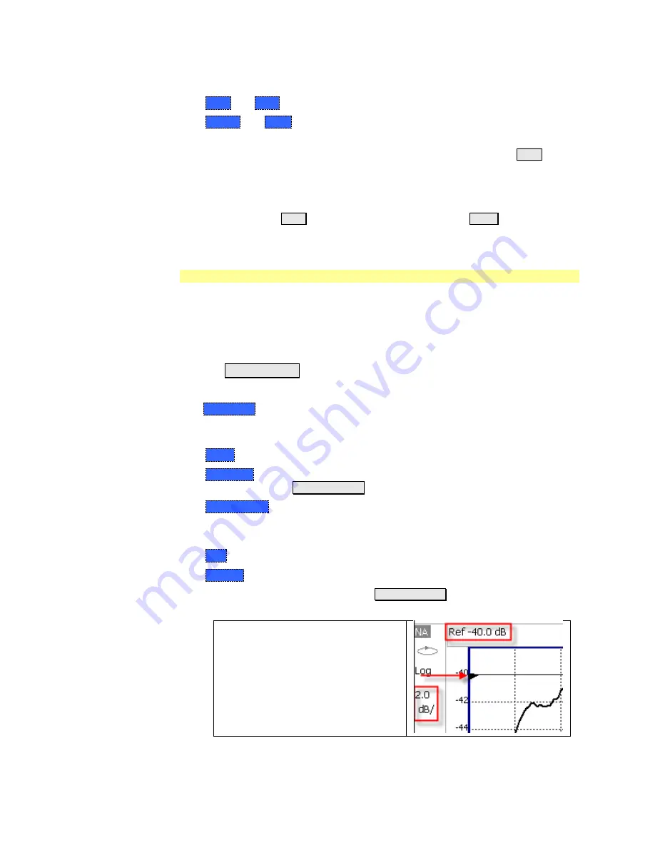
Scale annotation on the FieldFox
screen
Reference Line = red arrow
Ref Level = -40 dB
Ref Position = 1
Scale = 2 dB per division


