52
FieldFox User’s Guide
o
Man
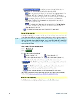
(default setting at -15 dBm) Set output power to an arbitrary value,
FLAT across the displayed FieldFox frequency span. If flattened power can
NOT be achieved, a
warning message
and beep occurs. To achieve a
flattened output power, reduce the power level or stop frequency.
o
Then press
Power Level
o
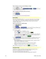
Then enter a value using the numeric keypad, the
▲
|
▼
arrows, or the rotary
knob.
o
Press
Enter
.
System Impedance (Z0)
To accurately view data presented in Smith Chart format, first set the System
Impedance.
Learn how to select Smith Chart format on page 44.
Learn how to make 75
Ω
measurements at the FieldFox Supplemental Online
Help:
http://na.tm.agilent.com/fieldfox/help/FieldFox.htm
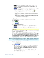
How to set System Impedance
Press
Meas Setup 4
.
Then
Settings
.
Then scroll to
System Z0
and press
Edit
Then type either
50
or
75
and press
Enter
Port Extensions
Port extensions allow you to electrically move the calibration reference plane on
either port 1 or port 2 after you have performed a calibration.
NOTE
FieldFox analyzers do NOT support port extensions for waveguide component
measurements.
Why use Port Extensions
Use port extensions if you are unable to perform a calibration directly at your
device because the location is not accessible. Perform a calibration at a
convenient place, then use port extensions to compensate for the time delay
(phase shift) to the desired reference plane. On the FieldFox, port extensions
does not compensate for the loss of the additional electrical length, nor any
mismatch errors beyond the calibration reference plane.
Also use port extensions if you have already performed a calibration, and then
decide that you need to add a length of transmission line in the measurement
configuration. Use port extensions to "tell" the FieldFox that you have added the
length to a specific port..
With S11 and S22 reflection measurements, the FieldFox doubles the port
extension valued that you enter to account for the additional delay in the
forward and reverse directions.
With S21 and S12 transmission measurements, the port 1 and port 2
extensions are added together. This accounts for the total transmission delay
going through ports 1 and 2.

