Time Domain - Option 010
59
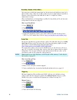
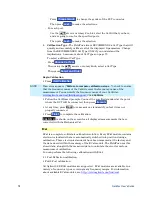
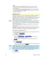
How to make Window setting
Press
Measure 4
Then
Transform
Then
More
Then
Transform Window
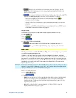
A settings table appears that allows you to navigate and select the following
settings. These settings are made exactly like those made on the Transform
Settings table. Learn how on page 56.
NOTE
Any of the following four methods can be used to make this same Window
setting. Impulse Width values are calculated from the frequency span and Kaiser
Beta value.
1.
Window
Min
Medium
Max
2.
Percent
0
50
100
3.
Kaiser Beta
0
6.50
13.00
4.
Impulse
Width
100.455 ps
168.501 ps
231.284 ps
Line Loss and Velocity Factor
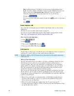
By default, the FieldFox does NOT correct Time Domain measurements to
account for the inherent loss of a cable. However, to make more accurate
measurements, Line Loss and Velocity Factor should be considered.
About Velocity Factor and Line Loss
o
Velocity Factor is a property of the physical material of a cable. A VF of 1.0
corresponds to the speed of light in a vacuum, or the fastest VF possible. A
polyethylene dielectric cable has VF = 0.66 and a cable with PTFE dielectric
has VF = 0.7.
o
Line Loss is specified in dB/m (or ft). In addition to the length of the cable,
loss is also directly proportional to the frequency of the signal that passes
through the cable.
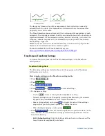
The following is an example showing how Line Loss works:
The DUT is a 100 meter transmission cable. The Line Loss value is .1
dB/meter. This means that a signal traveling ONE WAY through the cable will
lose 10 dB of power (100 m * .1dB/m). Because the FieldFox performs this
measurement with 1 port, the test signal travels down the cable and then back,
for a total loss of 20 dB.
For the purpose of illustrating this point, connect an OPEN to the end of the
cable – a maximum-sized fault - for 100% reflection of the 300 MHz test signal.
Without compensation
for the loss of the cable, a –20 dB response would be
visible at 100 meters, which is the OPEN at the end of the DUT. This is from 10
dB of loss through the cable in each direction.


