background image

22

Quiet Cover DS User Information

2

Installation

Installing the Hose

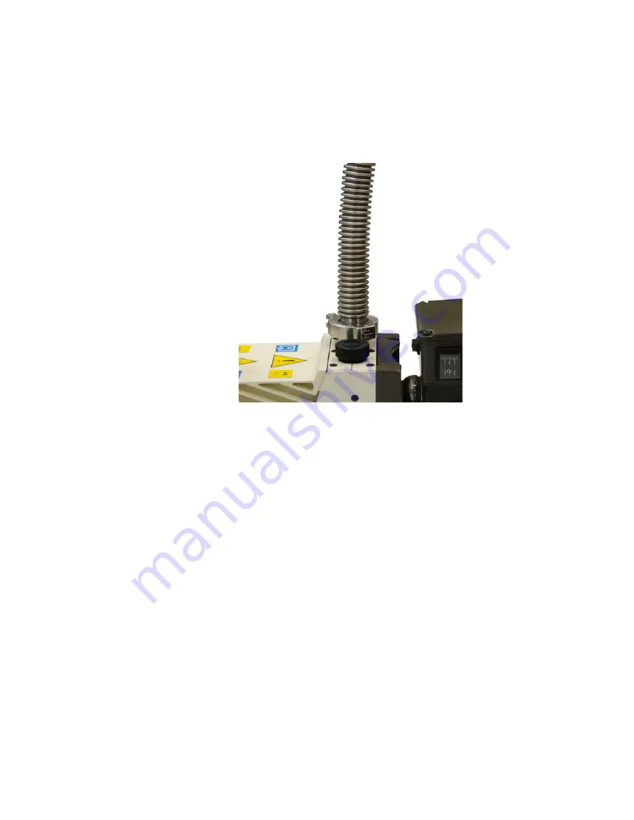
Install the pump hose to the rough pump (Figure 9)

Refer also to your rough pump documentation for more 
information.

Figure 9

Pump hose connected to the rough pump (DS 302 shown)

Summary of Contents for G6012A

Page 1: ...Agilent Technologies Agilent G6012A Quiet Cover DS User Information ...

Page 2: ...ess for a par ticular purpose Agilent shall not be liable for errors or for incidental or consequential damages in connection with the furnishing use or perfor mance of this document or of any information contained herein Should Agilent and the user have a separate written agreement with warranty terms covering the material in this document that conflict with these terms the warranty terms in the ...

Page 3: ...stalling the Oil Tray 16 Installing the Rough Pump Inside Quiet Cover DS 17 Installing the Mist Filter Extension 21 Installing the Hose 22 Installing the Lid 23 Installing the Pump Access Panels 24 Connecting the Power Supply 25 Verifying the Installation 26 3 Operation Front Panel Controls and Indicators 28 Handling Temperature Alarms 29 Changing Rough Pump Oil 30 Using the Kickstand 33 4 Trouble...

Page 4: ...4 Quiet Cover DS User Information ...

Page 5: ...shoot the G6012A Quiet Cover DS for GC MS LC MS and ICP MS rough pumps The Quiet Cover DS encloses your rough pump to significantly reduce noise while two internal fans ensure your pump will not overheat There is an easy to use kickstand and a full size oil tray to facilitate changing the oil There are also multiple access panels to easily access the pump for routine maintenance The Quiet Cover DS...

Page 6: ...ty system registered to ISO 9001 Information The Agilent Technologies Quiet Cover DS meets the following IEC classifications Category II Pollution Degree 2 Class III Quiet Cover DS has been designed and tested in accordance with recognized safety standards and is designed for use indoors If it is used in a manner not specified by the manufacturer the protection provided by the instrument may be im...

Page 7: ...d the intended use of the instrument Agilent Technologies assumes no liability for the customer s failure to comply with these requirements Table 1 lists the safety symbols that may appear on Quiet Cover DS Table 1 Safety symbols Description Symbol See accompanying instructions for more information Indicates a hot surface Pinch hazard Indicates earth ground terminal Indicates that you must not dis...

Page 8: ... Cover DS CAUTION While running Quiet Cover DS Do not block air flow to the fans Do not set items on top of Quiet Cover DS It is important that the Quiet Cover DS not recirculate hot air Always position the back end of the Quiet Cover DS where it can draw cool air CAUTION Be sure to position Quiet Cover DS so that there is plenty of room to allow access to panels and controls See Table 3 on page 1...

Page 9: ...sures Relocate the radio or antenna Move the device away from the radio or television Plug the device into a different electrical outlet so that the device and the radio or television are on separate electrical circuits Make sure that all peripheral devices are also certified Make sure that appropriate cables are used to connect the device to peripheral equipment Consult your equipment dealer Agil...

Page 10: ...ng To clean the oil tray 1 Reach under the front of Quiet Cover DS and pull out the tray 2 Wipe out excess oil with a clean lint free cloth 3 Wash the tray with a mild soap solution Recycling the Product For recycling contact your local Agilent sales office ...

Page 11: ... Table 2 Quiet Cover DS parts Part Quantity Part number Quiet Cover DS 1 G6012 64000 Oil tray 1 5188 1184 Mist filter extension 1 5188 1181 Clamp for mist filter extension 1 0100 0549 Seal for mist filter extension 1 0100 1597 Power supply 1 5188 1164 Figure 1 Quiet Cover DS front view Pump Access door Oil tray Back casters Front locking casters Mist filter extension with seal and clamp ...

Page 12: ...Information 1 Introduction NOTE See Figure 13 on page 28 for a view of the front panel controls Figure 2 Quiet Cover DS back view Kickstand Two fans Mist filter Pump access panel both sides Power cord connection Power supply ...

Page 13: ...Physical dimensions Weight 24 5 kg 54 lbs Dimensions Kickstand up 89 39 44 cm 35 15 4 17 3 in L W H Power supply AC input voltage 100 to 240 VAC 10 DC output voltage 24 V Output load max 1 25 A Input frequency 47 to 63 Hz Power consumption 11 W Rated current 450 mA Temperature and humidity ranges Ambient temperature 5 to 35 C 41 to 95 F Humidity 15 to 95 Altitude 4600 m 14950 ft ...

Page 14: ...14 Quiet Cover DS User Information 1 Introduction ...

Page 15: ...ling the Rough Pump Inside Quiet Cover DS 17 Installing the Mist Filter Extension 21 Installing the Hose 22 Installing the Lid 23 Installing the Pump Access Panels 24 Connecting the Power Supply 25 Verifying the Installation 26 This chapter describes how to assemble the Quiet Cover DS and install the rough pump ...

Page 16: ...il tray packaged separately You need to install it prior to using Quiet Cover DS To install it slide it into the bottom of Quiet Cover DS with the deep part of the tray forward There are a set of rails along the bottom edges of the frame that guide the tray into place Figure 3 Figure 3 Installing the oil tray Push in tray ...

Page 17: ...ough pump inside Quiet Cover DS 1 Remove the two pump access panels by loosening the thumbscrews on the top and sides 2 Remove the lid by loosening the thumbscrews on each side WARNING The pump May be hot Use gloves when moving it or wait until it is cool Is heavy For your safety two people should move it together ...

Page 18: ... For Agilent DS 202 and DS 302 pumps align the back edge of the vibration foam with the back end of the pump base Figure 4 Center the pump on the vibration foam Figure 4 Proper installation of the DS 202 302 pumps Vibration foam edge Pump base back edge ...

Page 19: ...sure that the sides of the pump base align with the sides of the vibration foam 4 Check your pump orientation inside the Quiet Cover DS The oil level window sight glass must face the front door of the Quiet Cover DS Make sure the pump power cord is not crimped or under the pump Figure 5 Proper installation of the DS 402 602 pumps Vibration foam Pump base front edge front edge ...

Page 20: ...uiet Cover DS frame and place the grommet around the pump power cord 6 Plug the pump power cord into the pump then slide the grommet with the power cord back into the groove on the back of the frame Figure 7 Figure 6 Grommet location on Quiet Cover DS Figure 7 Installed pump power cord DS 302 shown Grommet Grommet ...

Page 21: ...talled install it as follows 1 If necessary shut off the rough pump 2 Remove the existing mist filter if installed 3 Install the mist filter extension the new seal and clamps onto the outlet port 4 Install the mist filter with the seal and clamp onto the top of the extension Figure 8 Refer also to your rough pump documentation for more information Figure 8 Mist filter attached to rough pump DS 302...

Page 22: ...r Information 2 Installation Installing the Hose Install the pump hose to the rough pump Figure 9 Refer also to your rough pump documentation for more information Figure 9 Pump hose connected to the rough pump DS 302 shown ...

Page 23: ...uds posts on the inner wall of the top lid align with the grooves along the frame and the retained thumbscrews align with the screw holes Tighten the retained thumbscrews on both sides Figure 10 Figure 10 Placing the lid on Quiet Cover DS DS 302 shown Lid Retained thumbscrews on both sides Alignment grooves both ends on both sides ...

Page 24: ...panels place the access panels on the lid and base as shown in Figure 11 Align the retained thumbscrews with the screw holes along the frame and lid Tighten the retained thumbscrews on both panels Figure 11 Installing the pump access panels on Quiet Cover DS Retained thumbscrews on both sides Pump access panels ...

Page 25: ...er Supply Connect the power supply to the back of Quiet Cover DS by twisting the ring on the circular connector of the power cord Figure 12 Plug the pronged end of the power cable into the wall outlet Figure 12 Connecting the power supply Plug in power supply cord here ...

Page 26: ...the red light should not be lit If either are on remove the access panels and lid Refer to Chapter 4 Troubleshooting for more information There should be neither excessive noise nor vibration If either condition is true go back over each installation step to be sure everything was done correctly and all nuts are securely fastened The power cords should be positioned so as to not interfere with the...

Page 27: ...arms 29 Changing Rough Pump Oil 30 Using the Kickstand 33 To operate Quiet Cover DS you will need to Understand the controls and indicators on the front panel Know how to handle temperature alarms and signals Know how to drain oil from the rough pump and oil tray Be able to tilt the Quiet Cover DS using the kickstand for draining the oil ...

Page 28: ...3 shows the location of the On Off switch and indicators of the Quiet Cover DS front panel Figure 13 The front panel of Quiet Cover DS Power LED Green On Off switch Temperature Alarm LED Red Thumbscrew to release access door Thumbscrew to release access door indicates excessive heat when lit ...

Page 29: ...When this condition occurs remove the panels to cool the pump Check that both fans are turning and that air flow to the Quiet Cover DS is not restricted You cannot turn the alarm off It will stop when the temperature returns to an acceptable level See Troubleshooting on page 37 for more information NOTE It is important that the Quiet Cover DS not recirculate hot air Always position the back end of...

Page 30: ...perly prepare your system for release of primary vacuum 2 Turn off the rough pump 3 Turn off Quiet Cover DS 4 Unplug the power supply from the Quiet Cover DS 5 Open the front access door of Quiet Cover DS by loosening the retained thumbscrews 6 Lock the front locking casters to secure the Quiet Cover DS 7 Be sure the oil tray is securely seated 8 Tilt the Quiet Cover DS by using the kickstand loca...

Page 31: ...as completely drained 11 Carefully remove the oil tray and dispose of the oil according to local safety and environmental guidelines 12 Return the Quiet Cover DS to its untilted position See Using the Kickstand on page 33 13 Reinsert the oil tray See Installing the Oil Tray on page 16 Figure 14 DS 302 pump through access door other DS models are similar Sight glass Oil drain plug ...

Page 32: ...4 Remove the access panel over the oil fill plug and refill the pump Figure 15 Refer to the pump documentation for more information 15 Replace the pump access panel and close the access door Figure 15 Oil fill plug location DS 302 shown Oil fill plug ...

Page 33: ...tion 33 Using the Kickstand To tilt the Quiet Cover DS 1 Make sure the Quiet Cover DS is on a level surface 2 Lock the two front locking casters to secure the Quiet Cover DS Figure 16 Figure 16 Locking the front casters Front locking casters ...

Page 34: ...ning clip Figure 17 4 With the kickstand released from the clip step down on the horizontal bar until the Quiet Cover DS is in its tilted position Figure 18 Figure 17 Releasing the kickstand Figure 18 Quiet Cover DS in a tilted position Kickstand Retaining clip Horizontal bar Kickstand ...

Page 35: ...d gently push the Quiet Cover DS forward until it moves off of the kickstand To avoid dropping it stand on the kickstand as you lower the unit 2 Raise the kickstand and secure it with the retaining clip 3 If necessary unlock the front locking casters push the Quiet Cover DS back to its operating location and lock the front locking casters to secure the Quiet Cover DS CAUTION The kickstand s horizo...

Page 36: ...36 Quiet Cover DS User Information 3 Operation ...

Page 37: ...ct Temperature alarm does not turn off Check that ambient room temperature is below 35 C 95 F Remove the Quiet Cover DS access panels and lid Ensure there are no air restrictions and that adequate cool air is available to the Quiet Cover DS Check that both fans are turning Call your Agilent service representative if the lab temperature is within specifications Quiet Cover DS does not turn on Check...

Page 38: ...om temperature is above 35 C 95 F and the red over temperature LED is lit Call your Agilent service representative Do not continue to use your rough pump in the Quiet Cover DS the alarm may have failed The red over temperature LED is not lit even though the room temperature is above 35 C 95 F and the alarm is sounding Call your Agilent service representative Do not continue to use your rough pump ...

Reviews: