Operating in Chemical Ionization (CI) Mode
4
5977 Series MSD Operation Manual
103
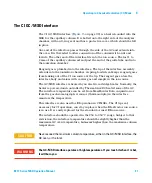
The
Open
and
Closed
states are shown in the monitors as
1
and
0
respectively.
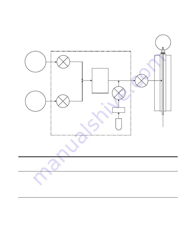
Figure 16
Reagent gas flow control module schematic
Table 18
Flow control module state diagram
Result
Gas A flow
Gas B flow
Purge
with Gas A
Purge
with Gas B
Pump out
flow module
Standby,
vented, or
EI mode
Gas A
Open
Closed
Open
Closed
Closed
Closed
Gas B
Closed
Open
Closed
Open
Closed
Closed
MFC
On
setpoint
On
setpoint
On
100%
On
100%
On
100%
Off
0%
Shutoff valve
Open
Open
Open
Open
Open
Closed
Gas A
(methane)
supply
Gas B
(other)
supply
Gas A
select valve
Gas B
select valve
Mass
flow
controller
Calibration
valve
Restrictor
Calibration
vial
Shutoff
valve
GC/MSD
interface
GC column
CI ion
source
Summary of Contents for G7035A
Page 1: ...Agilent Technologies Agilent 5977 Series MSD Operation Manual ...
Page 30: ...30 5977 Series MSD Operation Manual 1 Introduction ...
Page 88: ...88 5977 Series MSD Operation Manual 3 Operating in Electron Ionization EI Mode ...
Page 170: ...170 5977 Series MSD Operation Manual 6 CI Maintenance ...
Page 171: ......


