If the instrument passes both checks, the probability is greater than 90%
that
and
are functional: go to “Check Pulse Generator” or
continue with
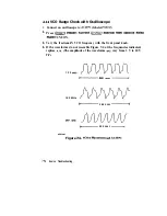
VCO Range Check with Oscilloscope” to
Fractional-N Analog and
Fractional-N Digital Check
with Spectrum
Analyzer
2. Set the parameters on the spectrum analyzer:
start frequency = 50 MHz
stop frequency = 250 MHz
bandwidth = 300
3. Remove the instrument bottom cover and disconnect the
cable from
the
Pulse Generator.
4. Connect the spectrum analyzer to the output of
via the
cable.
5. Slowly turn the network analyzer front panel knob to tune the signal across
the entire frequency range.
You should see a signal that is about 0
at 120 MHz and below. You
should see the signal drop approximately 2.5
above 120 MHz.
6. Look for sidebands on the signal.
The signal should appear very clean without any sidebands present, however,
you will observe source harmonics
If any sidebands do appear on the signal, there could be a faulty
fractional-N analog assembly.
If you see pieces of the signal dropping out (possibly in steps) when you are
tuning the signal across the frequency range, there could be a faulty
fractional-N digital assembly.
n
If a clean signal appears across the entire frequency range, you can assume
that the
(fractional-N analog) and the
(fractional-N digital)
assemblies are working correctly.
Source Troubleshooting
1
Summary of Contents for HP 8719D
Page 5: ...Service Guide i 8719D 2OD 22D Network Analyzer Ra HEWLETT PACKARD...
Page 44: ...Syetem Verifkatiin and 2 9 Perfonnanm Tests...
Page 69: ...234 Syotom riiiwtiin ad Rrfonnance Tests...
Page 95: ...This page is lejt intentionally blank Adjustments and Correction Constants 3 7...
Page 100: ......
Page 128: ......
Page 130: ......
Page 164: ......
Page 165: ...4 24 artTroubleshootingHen...
Page 166: ......
Page 167: ...4 26 Start Troubleshooting Hen...
Page 168: ......
Page 169: ......
Page 170: ......
Page 172: ...Power Supply Troubleshooting Flowchart 6 2 Power Supply Troubleshooting...
Page 192: ...6 22 Power Supply Troubleshooting...
Page 193: ......
Page 196: ......
Page 197: ...64 Digital Control Troubleshooting...
Page 198: ......
Page 199: ...6 6 Digital Control Troubleshooting...
Page 200: ...Digital Control Troubleshooting 6 7...
Page 222: ...Source Troubleshooting Flowchart 7 2 Source Troubleshooting...
Page 355: ...r G I _ i 1 2 Figure 13 1 Module Exchange Procedure 1 3 4 ReplaceableParts...
Page 359: ...Major EP 8719D 20D Assemblies lbp Armu 05 134 Replaceable Parts...
Page 360: ...Major EIP 8722D Assemblies lbp I f I i d 1 I Replaceable Parts 134...
Page 362: ...Major Assemblies Bottom IL IT n I 0 l J Replaceable Parts 13 11...
Page 363: ...Major Assemblies Bottom T 13 l 2 Replaceable Parts...
Page 366: ...HP 8722D Cables Ibp I vdK we w4 WZ W4q Wih w47 sbhllld Replaceable Parts 13 l 5...
Page 369: ...Cables Bottom 13 18 Replaceable Parts...
Page 370: ...Cables Bottom Replaceable Parts 13 18...
Page 371: ...Cables Bottom 13 20 ReplaceableParts...
Page 372: ...Cables Bottom Replaceable Parts 13 21...
Page 375: ...Cables Front 13 24 Replaceable Parts...
Page 376: ...Cables Front sbtlll d Replaceable Parts 13 25...
Page 380: ...Front Panel Assembly Inside 3 PLACE Replaceable Parts 13 28...
Page 382: ...Rear Panel Assembly stolu2d Replaceable Parts 13 31...
Page 384: ...Rear Panel Assembly Option lD5 Replaceable Parts 13 33...
Page 386: ...Hardware Ibp 3 PLkCEIr i_ FL IIE 4 PLAlIE 2 I _ 2 z 1 I J ReplaceableParts 1 3 3 5...
Page 388: ...Replaceable Parts 13 37...
Page 401: ...Line Fuse Assembly Replacement and Post Repair Procedures 14 5...
Page 403: ...Covers Assembly Replacement and Post Repair Procedures 14 7...
Page 405: ...Front Panel Assembly Assembly Replacement and Pest Repair Procedures 14 g...
Page 409: ...Display Lamp and Assembly Assembly Replacement and Post Repair Procedures 14 13...
Page 413: ...Rear Panel Interface Board Assembly Assembly Replacement and Post Repair Procedures 14 17...
Page 417: ...Source Assemblies L 1 PLACES 3 4 PLACE51 Assembly Replacement and Post Repair Procedures 14 21...
Page 421: ...A7BTl Battery n i _ A EB n7ETI _ _ Assembly Replacement and Post Repair Procedures 14 25...
Page 423: ...A 15 Preregulator Assembly Assembly Replacement and Pest Repair Procedures 14 27...
Page 425: ...A19 Graphics Processor Assembly Assembly Replacement and Post Repair Procedures 14 28...
Page 427: ...A3 Disk Drive Assembly Assembly Replacement and Post Repair Procedures 14 31...
Page 435: ...Bl Fan Assembly 4 PLXE 1 II Assembly Replacement and Post Repair Procedures 14 39...
Page 458: ......
Page 459: ......
Page 460: ......
Page 461: ...A l 6 Determining System Measurement Uncertainties...


