63-65
Pat
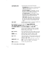
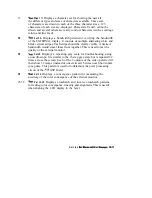
2-4. Displays a red, green, and blue pattern for verifying the
color purity of the display and also the ability to independently control
each color.
6 6
Fat
5.
Displays an all black screen. This is used to check for
stuck pixels.
6 7
Pat
6. Displays a
gray scale for verifying that the
GSP board can produce 16 different amplitudes of color (in this case,
white.) The output comes from the RAM on the GSP board, it is then
split. The signal goes thru a video DAC and then to an external monitor
or thru some buffer amplifiers and then to the internal LCD display. If
the external display looks good but the internal display is bad then the
problem may be with the display or the cable connecting it to the GSP
board. This pattern is also very useful when using an oscilloscope for
troubleshooting. The staircase pattern it produces will quickly show
missing or stuck data bits.
6 8
Pat
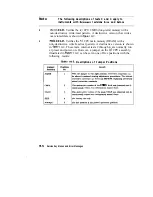
7. Displays the following seven colors. Red, Yellow, Green,
Cyan, Blue, Magenta and White.
69
Pat
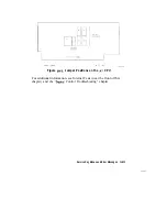
8. This pattern is intended for use with an external display.
The pattern displays a color rainbow pattern for showing the ability
of the
GSP board to display 15 colors plus white. The numbers
written below each bar indicate the tint number used to produce that
bar (0
red,
green,
blue).
7 0
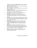
Pat
9. Displays the three primary colors Red, Green, and Blue at
four different intensity levels. You should see 16 color bands across
the screen. Starting at the left side of the display the pattern is; Black
four bands of Red (each band increasing in intensity) Black four bands
of Green (each band increasing in intensity) Black four bands of Blue
(each band increasing in intensity) Black If any one of the four bits for
each color is missing the display will not look as described.
Messages
Summary of Contents for HP 8719D
Page 5: ...Service Guide i 8719D 2OD 22D Network Analyzer Ra HEWLETT PACKARD...
Page 44: ...Syetem Verifkatiin and 2 9 Perfonnanm Tests...
Page 69: ...234 Syotom riiiwtiin ad Rrfonnance Tests...
Page 95: ...This page is lejt intentionally blank Adjustments and Correction Constants 3 7...
Page 100: ......
Page 128: ......
Page 130: ......
Page 164: ......
Page 165: ...4 24 artTroubleshootingHen...
Page 166: ......
Page 167: ...4 26 Start Troubleshooting Hen...
Page 168: ......
Page 169: ......
Page 170: ......
Page 172: ...Power Supply Troubleshooting Flowchart 6 2 Power Supply Troubleshooting...
Page 192: ...6 22 Power Supply Troubleshooting...
Page 193: ......
Page 196: ......
Page 197: ...64 Digital Control Troubleshooting...
Page 198: ......
Page 199: ...6 6 Digital Control Troubleshooting...
Page 200: ...Digital Control Troubleshooting 6 7...
Page 222: ...Source Troubleshooting Flowchart 7 2 Source Troubleshooting...
Page 355: ...r G I _ i 1 2 Figure 13 1 Module Exchange Procedure 1 3 4 ReplaceableParts...
Page 359: ...Major EP 8719D 20D Assemblies lbp Armu 05 134 Replaceable Parts...
Page 360: ...Major EIP 8722D Assemblies lbp I f I i d 1 I Replaceable Parts 134...
Page 362: ...Major Assemblies Bottom IL IT n I 0 l J Replaceable Parts 13 11...
Page 363: ...Major Assemblies Bottom T 13 l 2 Replaceable Parts...
Page 366: ...HP 8722D Cables Ibp I vdK we w4 WZ W4q Wih w47 sbhllld Replaceable Parts 13 l 5...
Page 369: ...Cables Bottom 13 18 Replaceable Parts...
Page 370: ...Cables Bottom Replaceable Parts 13 18...
Page 371: ...Cables Bottom 13 20 ReplaceableParts...
Page 372: ...Cables Bottom Replaceable Parts 13 21...
Page 375: ...Cables Front 13 24 Replaceable Parts...
Page 376: ...Cables Front sbtlll d Replaceable Parts 13 25...
Page 380: ...Front Panel Assembly Inside 3 PLACE Replaceable Parts 13 28...
Page 382: ...Rear Panel Assembly stolu2d Replaceable Parts 13 31...
Page 384: ...Rear Panel Assembly Option lD5 Replaceable Parts 13 33...
Page 386: ...Hardware Ibp 3 PLkCEIr i_ FL IIE 4 PLAlIE 2 I _ 2 z 1 I J ReplaceableParts 1 3 3 5...
Page 388: ...Replaceable Parts 13 37...
Page 401: ...Line Fuse Assembly Replacement and Post Repair Procedures 14 5...
Page 403: ...Covers Assembly Replacement and Post Repair Procedures 14 7...
Page 405: ...Front Panel Assembly Assembly Replacement and Pest Repair Procedures 14 g...
Page 409: ...Display Lamp and Assembly Assembly Replacement and Post Repair Procedures 14 13...
Page 413: ...Rear Panel Interface Board Assembly Assembly Replacement and Post Repair Procedures 14 17...
Page 417: ...Source Assemblies L 1 PLACES 3 4 PLACE51 Assembly Replacement and Post Repair Procedures 14 21...
Page 421: ...A7BTl Battery n i _ A EB n7ETI _ _ Assembly Replacement and Post Repair Procedures 14 25...
Page 423: ...A 15 Preregulator Assembly Assembly Replacement and Pest Repair Procedures 14 27...
Page 425: ...A19 Graphics Processor Assembly Assembly Replacement and Post Repair Procedures 14 28...
Page 427: ...A3 Disk Drive Assembly Assembly Replacement and Post Repair Procedures 14 31...
Page 435: ...Bl Fan Assembly 4 PLXE 1 II Assembly Replacement and Post Repair Procedures 14 39...
Page 458: ......
Page 459: ......
Page 460: ......
Page 461: ...A l 6 Determining System Measurement Uncertainties...


