146
6000 Series Oscilloscope User’s Guide
4
Triggering the Oscilloscope
Adjust the trigger level for the selected analog channel by
turning the Trigger Level knob. Press the
D15 Thru D0
key and
select
Thresholds
to set the threshold level for digital
channels. The value of the trigger level or digital threshold is
displayed in the upper-right corner of the display.
3
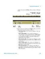
For each channel you select, press one of the condition
softkeys to set the condition for that channel in the pattern.
•
H
sets the pattern to high on the selected channel. A high
is a voltage level that is greater than the channel's trigger
level or threshold level.
•
L
sets the pattern to low on the selected channel. A low is a
voltage level that is less than the channel's trigger level or
threshold level.
•
X
sets the pattern to don't care on the selected channel.
Any channel set to don't care is ignored and is not used as
part of the pattern. However, if all channels in the pattern
are set to don't care, the oscilloscope will not trigger.
•
The rising edge (
) or falling edge (
) softkey sets the
pattern to an edge on the selected channel. Only one rising
or falling edge can be specified in the pattern. When an
edge is specified, the oscilloscope will trigger at the edge
specified if the pattern set for the other channels is true.
If no edge is specified, the oscilloscope will trigger on the
last edge that makes the pattern true.
For information regarding digital bus display when Pattern
triggering see
page 125
.
Specifying an Edge in a Pattern
You are allowed to specify only one rising or falling edge term in the pattern. If you
define an edge term, then select a different channel in the pattern and define
another edge term, the previous edge definition is changed to a don’t care.
Summary of Contents for InfiniiVision 6000 Series
Page 1: ...Agilent Technologies Agilent InfiniiVision 6000 Series Oscilloscopes User s Guide ...
Page 60: ...60 6000 Series Oscilloscope User s Guide 1 Getting Started ...
Page 126: ...126 6000 Series Oscilloscope User s Guide 3 Viewing and Measuring Digital Signals ...
Page 292: ...292 6000 Series Oscilloscope User s Guide 6 Displaying Data Interpreting Decoded LIN Data ...
Page 314: ...314 6000 Series Oscilloscope User s Guide 6 Displaying Data ...
Page 354: ...354 6000 Series Oscilloscope User s Guide 8 Reference ...
Page 362: ...362 6000 Series Oscilloscope User s Guide 9 ...


