Making Measurements
5
6000 Series Oscilloscope User’s Guide
227
4
Select the X and Y softkeys to make a measurement.
•
X Y
— Press this softkey to select either X cursors or Y
cursors for adjustment. The cursor currently assigned
to the Entry knob displays brighter than the other
cursors.
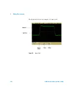
X cursors are vertical dashed lines that adjust
horizontally and normally indicate time relative to the
trigger point. When used with the FFT math function
as a source, the X cursors indicate frequency.
Y cursors are horizontal dashed lines that adjust
vertically and normally indicate Volts or Amps,
dependent on the channel
Probe Units
setting. When
math functions are used as a source, the measurement
units correspond to that math function.
•
X1
and
X2
— The X1 cursor (short-dashed vertical line)
and X2 cursor (long-dashed-vertical line) adjust
horizontally and indicate time relative to the trigger
point for all sources except math FFT (frequency is
indicated). In XY horizontal mode, the X cursors
display channel 1 values (Volts or Amps). The cursor
values for the selected waveform source are displayed
within the X1 and X2 softkeys.
The difference between X1 and X2 (
∆
X) and 1/
∆
X are
displayed on the dedicated line above the softkeys or in
the display area when some menus are selected.
Turn the Entry knob to adjust the X1 or X2 cursor
when its softkey is selected.
•
Y1
and
Y2
— The Y1 cursor (short-dashed horizontal
line) and Y2 cursor (long-dashed horizontal line) adjust
vertically and indicate values relative to the waveform's
ground point, except math FFT where the values are
relative to 0 dB. In XY horizontal mode, the Y cursors
display channel 2 values (Volts or Amps). The cursor
values for the selected waveform source are displayed
within the Y1 and Y2 softkeys.
Summary of Contents for InfiniiVision DSO6014L
Page 2: ...Agilent Technologies Agilent 6000 Series Oscilloscopes User s Guide...
Page 59: ...58 6000 Series Oscilloscope User s Guide 1 Getting Started...
Page 109: ...108 6000 Series Oscilloscope User s Guide 2 Front Panel Controls...
Page 125: ...124 6000 Series Oscilloscope User s Guide 3 Viewing and Measuring Digital Signals...
Page 251: ...250 6000 Series Oscilloscope User s Guide 5 Making Measurements...
Page 287: ...286 6000 Series Oscilloscope User s Guide 6 Displaying Data Interpreting Decoded LIN Data...
Page 321: ...320 6000 Series Oscilloscope User s Guide 7 Saving and Printing Data...
Page 370: ......

