62
6000 Series Oscilloscope User’s Guide
2
Front-Panel Controls
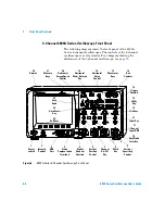
7. Probe Compensation Terminals
Use the signal at these
terminals to match each probe’s characteristics to the
oscilloscope channel to which it is connected. See
8. AutoProbe Interface
(Not available on 100 MHz bandwidth
models.) When you connect a probe to the oscilloscope, the
AutoProbe Interface attempts to determine the type of probe
and set its parameters in the Probe menu accordingly. See
. Note: Although the 100 MHz models lack the AutoProbe
interface, they do have a probe sense ring around the BNC.
Therefore, the probe attenuation factor will be automatically set
when you connect a compatible probe such as the 10073C or
10074C.
9. Channel Input BNC Connector
Attach the oscilloscope probe
or BNC cable to the BNC connector. This is the channel’s input
connector.
10. External Trigger Input
Allows you to trigger the oscilloscope
using an external signal. See
11. Trigger Output
This output is related to the oscilloscope’s
internal trigger signal. See
.
12. Calibration Protect Switch
Set this switch to “Protect” to
prevent unwanted re-calibration. See
13. 10 MHz Reference Input/Output
You can input a signal,
synchronizing multiple instruments, or you can output this
instrument’s reference signal. See
14. XGA Video Output
You can connect an external display to
the oscilloscope for viewing waveforms. See
C A U T I O N
Only connect USB devices to the USB host port. Do not attempt to
connect a host computer to this port to control the oscilloscope. Use
the USB device port if you want to connect a host (see the 6000 Series
Oscilloscope Programmer’s Quick Start Guide for details).
Summary of Contents for InfiniiVision DSO6014L
Page 2: ...Agilent Technologies Agilent 6000 Series Oscilloscopes User s Guide...
Page 59: ...58 6000 Series Oscilloscope User s Guide 1 Getting Started...
Page 109: ...108 6000 Series Oscilloscope User s Guide 2 Front Panel Controls...
Page 125: ...124 6000 Series Oscilloscope User s Guide 3 Viewing and Measuring Digital Signals...
Page 251: ...250 6000 Series Oscilloscope User s Guide 5 Making Measurements...
Page 287: ...286 6000 Series Oscilloscope User s Guide 6 Displaying Data Interpreting Decoded LIN Data...
Page 321: ...320 6000 Series Oscilloscope User s Guide 7 Saving and Printing Data...
Page 370: ......

