background image

Hints and Tips

7

Transmission Test Set Quick Reference Guide

75

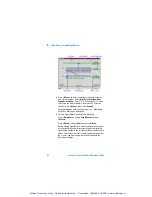
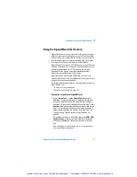
Front Panel Soft Recovery (Cold Start)

An instrument “cold start” routine is provided to reset the 
instrument in the event of an unplanned hardware or firmware 
event. AA cold start reboots the instrument and restarts the 
instrument using a default configuration file. Performing a cold 
start erases existing configuration information.

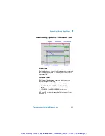
Performing a Cold Start

1

Switch the instrument off and wait a few seconds.

2

Switch the instrument on and as the instrument boots up, 
look carefully at the display.

3

Wait for the “Starting instrument” . . . . . text to be displayed. 
After a few seconds start to repeatedly press the 

<Menu>


key until the Agilent splash screen appears with an options 
menu in the top left corner of the display.

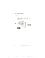
The following options are available:

1

Reload configuration.

3

Cold start.

5

Normal start.

6

Upgrade software.

4

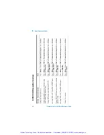
Press 3 on the numeric keypad to select cold start.

5

The unit will then continue with the boot up process.

6

When the boot-up procedure is complete, the instrument 
displays a dialog box with the message

“Instrument reset to default settings.”

Artisan Technology Group - Quality Instrumentation ... Guaranteed | (888) 88-SOURCE | www.artisantg.com

Summary of Contents for J2126A

Page 1: ...cess underutilized and idle equipment along with credit for buybacks and trade ins Custom engineering so your equipment works exactly as you specify Critical and expedited services Leasing Rentals Dem...

Page 2: ...Agilent J2126 7A Transmission Test Sets Quick Reference Guide Artisan Technology Group Quality Instrumentation Guaranteed 888 88 SOURCE www artisantg com...

Page 3: ...QRG_SONET1 book Page 16 Monday June 10 2002 11 39 AM Artisan Technology Group Quality Instrumentation Guaranteed 888 88 SOURCE www artisantg com...

Page 4: ...Agilent Technologies Agilent J2126 7A Transmission Test Sets Quick Reference Guide Artisan Technology Group Quality Instrumentation Guaranteed 888 88 SOURCE www artisantg com...

Page 5: ...in Should Agilent and the user have a separate written agreement with war ranty terms covering the material in this document that conflict with these terms the warranty terms in the separate agree men...

Page 6: ...conditions are fully understood and met In This Quick Reference Guide This guide contains information on The conventions used within this guide A Getting Started chapter for new users An introduction...

Page 7: ...l For example Test Functions Errors and Alarms indicates that you should choose Errors and Alarms from the Test Functions main menu Field items and drop down list entries appear in bold For example se...

Page 8: ...s and Alarm LEDs 23 Top Panel Tour 24 Optical Out Ports 24 Optical In Ports 25 Clock Ports 26 DCC Port 28 Electrical Test Ports 29 Ethernet Ports 30 Left Side Panel Tour 31 Right Side Panel Tour 32 Us...

Page 9: ...6 Using Smart Test and SignalWizard Shortcuts to Results Measurements and Stored Settings 60 Resetting Instrument to Default Settings 60 Using the SignalWizard Test Feature 61 Understanding SignalWiz...

Page 10: ...ions 80 SONET SDH Receiver Functions 82 SONET SDH Overhead Setup 84 SONET SDH Overhead Monitor 86 SONET SDH Results 88 SONET SDH Test Functions 90 Ethernet Functions 91 System Functions 92 System Func...

Page 11: ...8 Transmission Test Set Quick Reference Guide Artisan Technology Group Quality Instrumentation Guaranteed 888 88 SOURCE www artisantg com...

Page 12: ...ference Guide 1 Product Description Introduction 10 Option Guide 12 Alternative Optical Connectors available accessories 14 Ethernet Capability 11 Other Options 15 Accessories 15 Artisan Technology Gr...

Page 13: ...al test coverage SONET SDH PDH and T Carrier Full integrated all rate testing 52 Mb s to 10 Gb s optical 52 155 Mb s DS1 3 2 8 34 140 Mb s electrical Full range of standard and concatenated mappings A...

Page 14: ...ange of graphical results tools Comprehensive online help facilities Online User manual Context sensitive help for each control field Ability to add your own help documents Ethernet Capability Test da...

Page 15: ...26A 3 slot chassis J2127A 4 slot chassis J2127A 6 slot extended chassis Mainframe and Potential Test Rate Capability Mainframe Optical Test Interfaces Frequency Range J2126A see Note 1 OC 1 OC 3 OC 12...

Page 16: ...m 101 1310 1550 nm 102 Optical interfaces operating up to 10 Gb s 1550 nm 111 HS 121 SR 1310 nm 120 SR HS High Rx sensitivity optics SR Short reach optics Connector Option FC PC Adapters fitted on all...

Page 17: ...oduct is shown below Ethernet Options J7283A FC PC J7284A SC J7285A ST J2126A with option 100 101 2 2 2 J2126A with option 102 3 3 3 J2127A with option 100 101 and 111 120 121 5 5 5 J2127A with option...

Page 18: ...tended warranty options For access to Agilent Product information and sales service contacts please visit http www agilent com Accessories Additional Documentation J7280A Full set of printed manuals U...

Page 19: ...83A FC PC optical connector exchangeable J7284A SC optical connector exchangeable J7285A ST optical connector exchangeable J7281A DCC port converter cable 9 pin miniature D type to 37 pin D type RS 44...

Page 20: ...Tour 31 Right Side Panel Tour 32 Using a Mouse and Keyboard 34 Selecting SONET or SDH Operation 35 This chapter guides you round the many features of the instru ment It also includes information on ho...

Page 21: ...on Controls Keypad Press this button to start a new test period or terminate the current test period The LED indicator above the button is on when a test period is in progress Press this button to acc...

Page 22: ...trument display The Arrow Navigation buttons move the focus up down left right through menus drop down lists and the instrument display Press Select to enter any selected menu item or value you have e...

Page 23: ...cimal binary and hexadecimal entries are all made directly from the keypad Special keys used in numeric entries Numeric Entry Text Entry Help Function Keys Press Minus to enter a negative value for ex...

Page 24: ...use the F up arrow key to switch between lower case characters CapsOff upper case CapsOn and number Num The cur rent mode is displayed in the Status Line at the bottom right of the screen Special keys...

Page 25: ...have used the Back key for navigating then this key takes you forward to where you have come from Otherwise pressing this key has no effect Scrolls up through the displayed page Scrolls down through...

Page 26: ...r remains red for 100 ms then returns to off Operates on the foreground instrument SONET SDH Indicates that at least one SONET or SDH alarm is present Operates on the foreground instrument DSn Indicat...

Page 27: ...OC 48 OC 192 and SDH optical signals STM 0 STM 1 STM 4 STM 16 STM 64 at wavelength 1310 and 1550 nm depending on instrument model and options DCC Electrical Test Ports Optical Out Ports Optical In Po...

Page 28: ...dBm 10 Gb s 1550 nm SR Selectable optical connector see Optical Connectors prod uct options on page 13 for a 10 Gb s optical output Nomi nal wavelength is 1550 nm Power output is 5 to 1 dBm 10 Gb s 1...

Page 29: ...length 1200 to 1600 nm Input damage power 1 dBm never exceed maximum input power The rec ommended input power operating level for OC 192 STM 64 signals is 20 to 9 dBm 10 Gb s SR Optics Selectable opti...

Page 30: ...ominal connector for a DS1 BITS clock ref erence output Generated relative to the selected transmit ref erence clock TX Eye Clock 52 2 5 Mb s SMA connector providing a TX Eye Clock signal at 1 4 of th...

Page 31: ...t rates The instru ment acts as a DCE Data Communications Equipment sup plying the clock signal for both drop and insert operation Rates D1 D3 DCC 192 kb s D4 D12 DCC 576 kb s Signal Type Unipolar dif...

Page 32: ...s DS3 unbalanced Out port can be active for the E1 Transmit function 2 Mb s In 3 pin Siemens 120 ohm balanced connector for an E1 Receive or E1 Insert signal input Either this port or the 2 140 Mb s D...

Page 33: ...rs are provided each of which can sup port 10 Mb s or 100 Mb s data rates 1G Ethernet Ports Two Gigabit Interface Convertors GBICs are provided as fol lows Tx Eye Clock SMA connector providing a TX Ey...

Page 34: ...ntrolled via the GPIB control bus External Protective Earth Connect an external earth connection to the instrument at this point Floppy Disk Drive Accepts 1 44 MB IBM formatted disks Floppy Disk Drive...

Page 35: ...ompliance with EN 55011 1991 a category 5 STP patch lead RJ45 cable should be used to connect to the LAN port Mouse PS 2 port for connecting a mouse Activation of this port is planned as a future enha...

Page 36: ...Remote Control port providing following configurations Controller Type Computer and Terminal Protocol None and Xon Xoff Speed 110 300 600 1200 2400 4800 9600 19200 38400 baud Parity Odd Even 1s 0s Sto...

Page 37: ...e front panel keypad to enter data The keyboard can be connected to the instrument at any time Keyboard Power On Off Mouse NOTE NOTE If you connect the keyboard to the Mouse Port PS 2 the keyboard wil...

Page 38: ...ment is a dual standard SONET SDH instrument Select the standard you require as follows 1 Press the Menu key and select System Preferences 2 Press Select to open the Preferences window Select SONET or...

Page 39: ...2 Getting Started 36 Transmission Test Set Quick Reference Guide Artisan Technology Group Quality Instrumentation Guaranteed 888 88 SOURCE www artisantg com...

Page 40: ...face GUI with windows menus and dialogs provides easy access to all the instrument setup moni toring and results pages together with constant display of con text sensitive help and instrument status T...

Page 41: ...field The title of the current displayed page is given at the top of the window in the title bar This also gives the menu name that the page has come from for example Overhead Setup Trace Mes sages is...

Page 42: ...s a comprehensive built in help system This is accessed at any time by pressing Help To close the help just press Help again The online help is displayed in a full size window NOTE The Help button tog...

Page 43: ...nu will automatically be displayed To select an item from the menu use the up down arrow navi gation buttons to move the focus through the main menu and the left right arrow navigation buttons to move...

Page 44: ...Select Use the arrow navigation buttons to highlight your choice then press Select To close the drop down list without making a selection press Cancel Drop down lists are used where multiple choices...

Page 45: ...lder tab move the highlight onto it Text entry box move the highlight onto the control field For quick text entry use the keypad which will be in text mode See Keypad on page 20 for details on how to...

Page 46: ...llows you to select individual digits and edit them using the keypad This is useful when you want to edit one digit of an eight digit number Press Select to enter the value Each time you enter a new v...

Page 47: ...ow The Cancel button can also be used to quickly close the window please note that this does NOT cancel any changes or settings you have made More button this is indicated by three dots and is used to...

Page 48: ...pping Press Select when you have finished or press Cancel to close the mapping diagram without changing the settings An example of a mapping diagram is shown below Checkboxes these are used to set a c...

Page 49: ...3 Using the Graphical User Interface 46 Transmission Test Set Quick Reference Guide Artisan Technology Group Quality Instrumentation Guaranteed 888 88 SOURCE www artisantg com...

Page 50: ...and Using Your Own Help Files 49 The Online Help provides you with full information on how to set up and use the instrument A comprehensive index and glossary are included One of the main features of...

Page 51: ...on your PC When there is more information on a page than can be viewed at any one time use the Prev Page and Next Page keys to scroll the display Pressing Menu displays a drop down list of the main c...

Page 52: ...nstrument and access them through the Online Help system This may be a useful tool if you wish to store specific instructions for your technicians to carry out routine procedures help them with proble...

Page 53: ...ll the documents and images in one folder directory The instrument does not currently support file tree struc tures Total size of the files should not be more than 1 44Mb The following procedure was u...

Page 54: ...w file and create a hypertext link from this file to each of your help files 6 Save the document as HTML You must name this index file ownhelp html It is important that you use this name as it is used...

Page 55: ...the Operation field and choose Refresh List Move the focus to the Action field and press Select to refresh the list of files 6 Select the Operation field and choose Copy all files to User Help 7 Move...

Page 56: ...from the instrument to a floppy disk 1 Insert a floppy disk into the disk drive on the left side of the instrument 2 Press Menu and select System File Manager 3 Press Select to open the File Manager...

Page 57: ...y disk 1 Press Menu and select System File Manager 2 Press Select to open the File Manager window 3 Select the User Help folder as shown 4 Set the Drive field to Internal or Floppy as required 5 Selec...

Page 58: ...Quick Reference Guide Agilent Technologies 5 Using Multiple Instruments Products Supported 56 Feature Summary 56 Foreground Instrument Selection 57 Artisan Technology Group Quality Instrumentation Gu...

Page 59: ...keys operate on the foreground instru ment The front panel Signal Frame Pattern Errors SONET SDH DSn PDH and History LEDs operate only on the foreground instrument The Multiple Instruments LED indica...

Page 60: ...ame of the selected foreground instrument is shown at the top of the main menu A combined SONET SDH Trouble Scan and Ethernet Results Summary report is available Press Menu choose Multiple Instruments...

Page 61: ...5 Using Multiple Instruments 58 Transmission Test Set Quick Reference Guide Artisan Technology Group Quality Instrumentation Guaranteed 888 88 SOURCE www artisantg com...

Page 62: ...Test to access the SignalWizard feature when the foreground instrument is set to SONET SDH or to the RFC Conformance Tests when set to Ethernet It also pro vides shortcuts to results measurements and...

Page 63: ...s Select an item from the list and press Select 2 Select an item from the list of shortcuts Resetting Instrument to Default Settings You can use the Smart Test to reset the instrument to its default v...

Page 64: ...being carried by equipped channels For information on connecting to a network when testing with SignalWizard see In Service Testing on page 68 Out of Service Testing on page 69 To monitor a signal wi...

Page 65: ...nitoring Path Trace Messages on page 66 3 To close SignalWizard do one of the following Press Smart Test choose Stop Wizard then press Select Press Menu choose Exit then press Select Before closing Si...

Page 66: ...te message formats are supported Overhead Viewer Displays results information associated with the overhead layer of the signal including Synchronization status message decoded S1 byte CV S RS BIP CV L...

Page 67: ...r The Overview window shows a summary using color coding see the following table of the results for all channels Each channel detected in the signal is provided with a dedicated box that summarizes th...

Page 68: ...P Remote Path Alarm RDI P Pointer Adjustment LOP LOP flashes blue on each adjust ment Color Coding Result Green No Errors Alarms detected during test or since the last history reset Red Errors Alarms...

Page 69: ...als have been pro tected in fault conditions You can view all the J1 path trace messages for the received signal at the same time Alternatively you can view all the J2 path trace messages associated w...

Page 70: ...annel for further analysis 2 Press Menu choose Expand then press Select This expands the VT TU substructure 3 Press Menu choose Collapse then press Select This closes the VT TU substructure NOTE STS A...

Page 71: ...d to simultaneously monitor all chan nels in the received signal This feature is useful when com missioning new transmission systems or performing routine maintenance checks A typical in service netwo...

Page 72: ...k element Applying a test signal to the line side of the network element may reduce the number of ports that need to be checked Sig nalWizard will identify the type of network paths present in the rec...

Page 73: ...6 Using Smart Test and SignalWizard 70 Transmission Test Set Quick Reference Guide Artisan Technology Group Quality Instrumentation Guaranteed 888 88 SOURCE www artisantg com...

Page 74: ...ence Guide 7 Hints and Tips Avoiding Problems When Making Measurements 72 Avoiding Optical Receiver Overload 73 Cleaning Optical Connectors 74 Front Panel Soft Recovery Cold Start 75 Artisan Technolog...

Page 75: ...r a long term test ensure that the equipment is not in a position where people will disturb the connecting fibers Ensure that all fiber connections are clean and dirt free Use a fiberscope to measure...

Page 76: ...ming tests it is recommended that you drive the optical receiver with a signal that has an average power in the middle of the receiver s operating range mid way between the upper and lower levels prin...

Page 77: ...by suitably trained service personnel 5 Apply some isopropyl alcohol to a piece of the cleaning paper and clean the barrel of the adapter Using a new piece of cleaning paper clean the face of the adap...

Page 78: ...e instrument boots up look carefully at the display 3 Wait for the Starting instrument text to be displayed After a few seconds start to repeatedly press the Menu key until the Agilent splash screen a...

Page 79: ...7 Hints and Tips 76 Transmission Test Set Quick Reference Guide Artisan Technology Group Quality Instrumentation Guaranteed 888 88 SOURCE www artisantg com...

Page 80: ...ead Setup 84 SONET SDH Overhead Monitor 86 SONET SDH Results 88 Ethernet Functions 91 System Functions 92 SystemFunctions MeasurementLogging 93 System Functions File Manager 94 Only the main selection...

Page 81: ...lowing Function Using Smart Test Path SignalWizard With SONET SDH as Foreground instrument Press Smart Test choose SignalWizard then press Select Ethernet RFC 2544 conformance tests With Ethernet as F...

Page 82: ...oose Destination Printer or File Function Multiple Instruments Path Select Foreground instrument Press Menu choose Multiple Instruments Select then press Select Choose SONET SDH or Ethernet then press...

Page 83: ...smitter Settings then press Select Then select SDH SONET Inserting 2 Mb s or DS1 into SDH or SONET signal Press Menu choose Tx Rx Transmitter Settings then press Select Then select SDH SONET Setting T...

Page 84: ...DH Setting Thru Mode Press Menu choose Tx Rx Thru Mode then press Select Coupling Transmit and Receive Settings Press Menu choose Tx Rx Coupling then press Select Recall or Save instrument configurati...

Page 85: ...ttings then press Select Then select SDH SONET Dropping 2 Mb s or DS1 from SDH or SONET signal Press Menu choose Tx Rx Receiver Settings then press Select Then select SDH SONET Setting Rx PDH DSn fram...

Page 86: ...s Select an item from the list and press Select Using SignalWizard Press Smart Test choose SignalWizard then press Select Coupling Receive and Transmit Settings Press Menu choose Tx Rx Coupling then p...

Page 87: ...nc Sta tus Press Menu choose Overhead Setup Labels then press Select Setting Tx Overhead APS Messages Press Menu choose Overhead Setup APS Messages then press Select Setting Tx Overhead H4 Sequence Pr...

Page 88: ...en press Select Setting Tx Signaling Bits Press Menu choose Overhead Setup Signaling Bits then press Select Restore Byte Default values Press Menu choose Overhead Setup Restore Defaults then press Sel...

Page 89: ...rhead Monitor Labels Signal Labels Sync Status Press Menu choose Overhead Monitor Labels then press Select Using Rx Overhead Monitor APS Messages Press Menu choose Overhead Monitor APS Messages then p...

Page 90: ...ts Press Menu choose Overhead Monitor Spare Bits then press Select Setting Rx Signaling Bits Press Menu choose Overhead Monitor Signaling Bits then press Select Setting Rx Sa Bits Press Menu choose Ov...

Page 91: ...or Summary then press Select View Measurement Errors Press Menu choose Results Errors then press Select View Performance Analysis Press Menu choose Results Performance Analysis then press Select View...

Page 92: ...e Results Signal Quality then press Select Select the Optical Power tab Measure Pulse mask Press Menu choose Results Signal Quality then press Select Select the Pulse Mask tab View graph of Pointer mo...

Page 93: ...t Functions Frequency Offset then press Select Adding Pointer Adjustments Press Menu choose Test Functions Pointer Adjustment then press Select Inserting Dropping Data Communications Channel Press Men...

Page 94: ...enu choose Tx Rx Stored Settings then press Select View Results Summary Press Menu choose Test Functions Results Results Summary then press Select Select Measurement Timing Press Menu choose Test Func...

Page 95: ...nced RDI enable SignalWizard Labelling Laser Off on power up STS 1 numbering Save System Preferences settings as default Press Menu choose System Preferences then press Select Audio Controls Beep on E...

Page 96: ...tem Measurement Logging then press Select Select Destination File or Printer Set up Logging Interval Report Press Menu choose System Measurement Logging then press Select Select Interval Report Select...

Page 97: ...get Screen Dumps from floppy disk drive A Press Menu choose System File Manager then press Select Select the Screen Dump tab Copy to or get Stored Settings from floppy disk drive A Press Menu choose S...

Page 98: ...1310 nm port 25 52 Mb s 2 5 Gb s 1550 nm port 25 A Accessories 15 Adapters 16 Additional documentation 15 Alarm LEDs 23 Arrow navigation buttons 19 Avoiding optical receiver overload 73 Avoiding prob...

Page 99: ...ing Tandem Connection Monitoring TCM receiver setup 82 transmitter setup 81 Ethernet Capability 11 External protective earth terminal 31 F Feature summary Multiple Instruments 56 Floppy disk drive 31...

Page 100: ...nted manuals 15 J7281A DCC port converter cable 16 J7283A FC PC optical connector 16 J7284A SC optical connector 16 J7285A ST optical connector 16 J7286A hard transit case 15 J7287A hard transit case...

Page 101: ...Optical In ports 25 Optical interfaces 13 Optical Out ports 24 Optical receiver overload avoiding 73 Option guide 12 Option UK6 calibration certificate 15 Options Ethernet 14 Own help files 49 P Perfo...

Page 102: ...covery cold start 75 SONET SDH In port 29 SONET how to select 34 SONET SDH Capability 10 SONET SDH Out port 29 Status and alarm LEDs 23 T Text entry box 42 Text entry keys 21 Top panel tour 24 Transit...

Page 103: ...100 Transmission Test Set Quick Reference Guide Artisan Technology Group Quality Instrumentation Guaranteed 888 88 SOURCE www artisantg com...

Page 104: ...QRG_SONET1 book Page 16 Monday June 10 2002 11 39 AM Artisan Technology Group Quality Instrumentation Guaranteed 888 88 SOURCE www artisantg com...

Page 105: ...quick reminder of how to use the Transmission Test Sets It is aimed at both new and experienced users Printed in UK 09 02 J2127 90011 Artisan Technology Group Quality Instrumentation Guaranteed 888 8...

Page 106: ...uipment Have surplus equipment taking up shelf space We ll give it a new home Learn more Visit us at artisantg com for more info on price quotes drivers technical specifications manuals and documentat...

Reviews: