background image

Breakout Box, LEDs, and Connectors

B

Advisor Mainframe Features System Guide

63

with existing data signals. In this case, you would want to open 
the DTE switch to isolate the circuit being tested from the 
internal data transmitter.

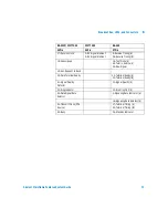
In monitor mode, the inputs to all V-Series signal receivers 
represent only 1/5 of a standard load, minimizing circuit 
loading effects. In Simulating and BERT testing modes, the 
transmitters are configured with normal source impedance.

Mark/Space Indicator

You can use the Mark/Space Indicator to test the state of any 
circuit on an RS-232/V.24 interface. The Mark/Space Indicator 
has two test jacks, which are connected together electrically. To 
do this, simply jumper from any test jack on either of the lateral 
or vertical switch banks to either of the Mark/Space Indicator 
jacks and observe the results. If the incoming signal is more 
positive than +3.0 volts, the Space LED lights. If the incoming 
signal is more negative than -3.0 volts, the Mark LED lights. If 
the Mark and the Space LEDs both light up, the incoming signal 
is actively changing states. This is normal for data and clock 
signals, but indicates a problem for control signals.

N O T E

Pin 1 of the RS-232 test port is Frame Ground or Protective Ground. It is 
connected to the case of the Advisor and, through the third wire of the 
power cable, to Ground. If you have a data circuit that requires isolation of 
Frame Ground, use the forward RS-232 test port and open switch 1 on the 
lateral switch bank

Pin 7 of the rearward RS-232 test port is Signal Ground, and it is isolated 
from Frame Ground by 100 KOhms to minimize ground-loop problems.

N O T E

EIA-232D (Formerly RS-232C) specifications consider interface signals in 
the range of -3.0 to +3.0 volts to be indeterminate (or not valid). Consistent 
with this recommendation, the Mark/Space Indicator treats signals in this 
range as “not present” and gives no indication.

Summary of Contents for J2300D

Page 1: ...underutilized and idle equipment along with credit for buybacks and trade ins Custom engineering so your equipment works exactly as you specify Critical and expedited services Leasing Rentals Demos In...

Page 2: ...Agilent Technologies Advisor Mainframe Features System Guide...

Page 3: ...r errors contained herein or for incidental or consequential damages in connection with the furnishing performance or use of this material Warranty A copy of the specific warranty terms applicable to...

Page 4: ...d repair of this instrument Failure to comply with these precautions with specific warnings in this manual violate safety standards of design manufacture and intended use of this instrument Grounding...

Page 5: ...areil sans le consentement de Agilent est formellement interdit Le fait de proc der de tels modifications sans autorisation pourrait entra ner l annulation de la garantie de l appareil ou de tout cont...

Page 6: ...jurisdictions Agilent s consent may not be required for limited disassembly or decompilation Upon request you will provide Agilent Technologies with reasonably detailed information regarding any disa...

Page 7: ...ng on the Advisor starting measurements and connecting peripheral devices to the Advisor are covered 3 Installing Removing Interface Modules This chapter explains how to install and remove several dif...

Page 8: ...e various specifications for the Agilent Advisor B Breakout Box LEDs and Connectors This appendix gives you specific information about the Advisor s Breakout Box LEDs and Connectors C Regulatory Infor...

Page 9: ...8 Advisor Mainframe Features System Guide...

Page 10: ...Mode 25 Connecting a Printer 26 3 Installing Removing Interface Modules Installing Interface Modules 28 Removing Interface Modules 29 4 Attaching Removing Undercradles Tools Required 32 Attaching an...

Page 11: ...A Specifications Physical Specifications 52 Operating Conditions 53 J2300D E Specifications 54 J3446D E Specifications 56 The Keyboard and Button Mouse 58 B Breakout Box LEDs and Connectors RS 232 V...

Page 12: ...ace Module 88 J2908A DDS 4 Wire Interface Module 89 J2909A ATM DS 3 E3 Interface Module 90 J2912A ATM OC 3c STM 1 Interface Module 91 J2912B ATM OC 3c STM 1 Interface Module 92 J2913A ATM 155 UTP Inte...

Page 13: ...12 Advisor Mainframe Features System Guide Contents J5457A High Speed V Series Interface Module 109 Laser Safety Statements 110 Safety Information for Laser Source Modules 111 Index...

Page 14: ...13 Agilent Technologies 1 Mainframe Overview Introduction 14 Product Matrix 15...

Page 15: ...D Advisors The J2300D and J3446D Advisors have AMD K6 2 chip 300 MHz processor 128 Mbytes of PC memory 1 44 MB flexible disk drive 4 GB or larger hard drive Model E Advisors The J2300E and J3446E Advi...

Page 16: ...46E Fast Ethernet LAN Mainframes J2295A X X J2306A Ethernet LAN X X J2306B Ethernet LAN X X J2307A Token Ring LAN X X J2309A Ethernet TR LAN X X J2309B Ethernet TR LAN X X J2524A FDDI X X J2527A TIMS...

Page 17: ...RI E1 X X J2294D T1 E1 X X J2296B PRI E1 X X J2296D E1 X X J2297B PRI E1 X X J2298B PRI T1 X X J2298D T1 E1 X X J2299B PRI T1 X X J2904B ISDN BRI S T X J2905B ISDN BRI S T U X J2908A DDS 4 Wire X J290...

Page 18: ...stem Guide 17 Interface Module J3446D J3446E Fast Ethernet LAN Mainframe J3447A 100BaseFX X Interface Module J2300D J2300E WAN Mainframes and J3446D J3446E LAN Mainframes with J3444A Undercradle Media...

Page 19: ...18 Advisor Mainframe Features System Guide 1 Mainframe Overview...

Page 20: ...Started Powering on the Advisor 20 Starting the Advisor the First Time 21 Setting the Date and Time 22 Starting an Advisor Application 23 Connecting an External Display Monitor 24 Setting VGA Display...

Page 21: ...r on The ON OFF power switch is located on the left side adjacent to the power cable connector If the mainframe will not power up check the following Power cable connections are good AC power is avail...

Page 22: ...o enter a first and last name and to accept the Microsoft Windows license agreement 3 Enter the Microsoft Windows authenticity product ID affixed to the mainframe 4 When the Date Time Properties dialo...

Page 23: ...ions and reports generated by the Advisor It is important to set your local time and date when you receive your Advisor Setting the time and date also updates system configuration files The time and d...

Page 24: ...plications can be started from Windows desktop Depending on the type of mainframe you have and any undercradles or modules you have installed the available applications will be displayed on the Start...

Page 25: ...is SVGA resolution 800x600 If you want to adjust the display to a higher resolution you must explicitly change the display mode to External Monitor Only To connect an External Display Monitor 1 Turn o...

Page 26: ...ing Started 2 Advisor Mainframe Features System Guide 25 Setting VGA Display Mode You can either disable or enable VGA Expansion Mode under Utilities on the Start menu Disable or enable VGA Expansion...

Page 27: ...files help topics and measurements results The default printer selection is No Printer If you want to use a printer with your Advisor you must select the printer driver and output port 1 Connect a pri...

Page 28: ...27 Agilent Technologies 3 Installing Removing Interface Modules Installing Interface Modules 28 Removing Interface Modules 29...

Page 29: ...fer to Chapter 1 for supported Interface Module configurations with the Advisor and Undercradles 1 Make sure the Module Release Latch is in the Install Remove Position 2 Slide the Interface Module or...

Page 30: ...face Modules 1 Press the left end of the Module Release Latch labeled PUSH TO UNLOCK then slide the latch toward the left Install Remove Position 2 Pull the Interface Module or Filler Panel out of the...

Page 31: ...30 Advisor Mainframe Features System Guide 3 Installing Removing Interface Modules...

Page 32: ...31 Agilent Technologies 4 Attaching Removing Undercradles Tools Required 32 Attaching an Undercradle 33 Removing an Undercradle 34 Using the Empty J2295A Undercradle 35...

Page 33: ...crews for the undercradle 2 Torx screws not needed for J2300D E and J3446D E 1 Right side endcap expander 1 Torx wrench 1 Small flat endcap 1 connector board 2 Grounding Strips not needed for J2300D E...

Page 34: ...ed in the miscellaneous parts kit or a T10 Torx screwdriver to remove the screws 2 Slide the metal plate over to the next set of drilled holes in the metal plate and re attach it with the same screws...

Page 35: ...t 5 Place the mainframe on top of the undercradle matching the connector on the bottom of the mainframe to the connector on the top of the undercradle 6 Push in the four silver tabs locking the underc...

Page 36: ...Refer to Removing an Undercradle on page 34 2 Turn the undercradle upside down with the four black feet facing up 3 Carefully remove the four black rubber feet using a small flat screwdriver to pull t...

Page 37: ...disconnect it from the standoffs 2 Turn the connector board over and fasten the card s in the slots provided 3 Press the connector board onto the standoffs The cards should be underneath the connector...

Page 38: ...stalling one printed circuit card insert the small flat endcap in the left side piece before you put it on the undercradle 3 If you are installing full length printed circuit cards insert the endcap e...

Page 39: ...38 Advisor Mainframe Features System Guide 4 Attaching Removing Undercradles...

Page 40: ...39 Agilent Technologies 5 Recovering Re installing Software Installing Windows 98 From the Hard Drive Image 40 Installing Upgrading Advisor Software 42 Viewing Electronic Documentation 42...

Page 41: ...is manual for instructions to install the operating system from the hard drive image When you install Windows 98 Second Edition you will be reformatting the C drive You will lose all installed applica...

Page 42: ...indows and properly shut down before continuing 3 Insert the Advisor Installation Preparation Disk for HD Recovery into the floppy drive 4 Turn on the Advisor and wait while the installation process s...

Page 43: ...shipped with your order all the Advisor documentation is also included in PDF format on the Software CD so you can select the documentation in addition to software applications to install on your hard...

Page 44: ...43 Agilent Technologies 6 Using Modem Ethernet PC Cards Introduction 44 Installing and Removing PC Cards 45 PC Card Modems 50...

Page 45: ...or enhanced I O capability with the Advisor software This includes functions such as a modem a LAN interface and a CD ROM Drive While integrated I O is the primary focus for the PC Card slot it can al...

Page 46: ...pt default PC Card drivers then press Enter to close the PC Card Wizard If you are using a supported Modem or NIC PC Card the drivers for these devices are already installed on your Advisor If you are...

Page 47: ...rming that the system recognizes a PC Card has been inserted 4 To verify that the system has properly identified the card check the system properties of the installed PC Card On the desktop right clic...

Page 48: ...ses an interrupt Windows will generally assign interrupt 15 to the card if it is available If this interrupt is not available Windows will assign the next available interrupt If a PC Card uses I O Add...

Page 49: ...pace COM4 Interrupt 11 and memory region CC000 CCFFF PC Functions Interrupt Analyzer Functions Interrupt Keyboard Controller 1 Ethernet or Ethernet Token Ring Undercradle 10 Programmable Interrupt Con...

Page 50: ...8 37F LPT1 Parallel 070 RTC Index NMI Mask 388 38B Sound H W 071 RTC Data Port 3B0 3BB Video Registers 080 09F DMA Page Register 3C0 3DF Video Registers 0A0 0A1 PIC 2 3E0 3E1 PC Card Controller 0C0 0D...

Page 51: ...tory is set at area code 719 and country USA Change these and any other settings to meet your requirements The modem can be connected to a standard telephone line through an RJ 11 phone jack Transmiss...

Page 52: ...51 Agilent Technologies A Specifications Physical Specifications 52 Operating Conditions 53 J2300D E Specifications 54 J3446D E Specifications 56 The Keyboard and Button Mouse 58...

Page 53: ...kg 3 1 lbs 1 40 kg 3 1 lbs 2 0 kg 4 4 lbs 1 49 kg 3 3 lbs 2 0 kg 4 4 lbs 2 08 kg 4 6 lbs 1 97 kg 4 35 lbs Dimensions J2300D J2300E J3446D J3446E Mainframe 11 44H x 31 43W x 31 75D cm 1 75H x 12 375W...

Page 54: ...C 41o F to 104o F 25o C to 60o C 13o F to 140o F Humidity Operating Storage 20 to 80 relative humidity non condensing to 40o C 10 to 90 relative humidity to 60o C Altitude Operating Storage 4 575 met...

Page 55: ...Appendix B for connector pinouts MIC F EXT Left Side of J2300D E Advisor MONITOR SERIAL PORT A B C RS 232 RS 232 D PARALLEL PORT PHONES G H E Front A On Off Switch B Power cable receptacle C Two RS 23...

Page 56: ...dercradles that you can use with the J2300D E V 35 HANDSET RS 449 INSTALL REMOVE POSITION LOCKED POSITION SEE MANUAL A B C D E F G 2 1 Front Right Side of J2300D E Advisor A 3 1 2 inch high density fl...

Page 57: ...to Appendix B for connector pinouts A B C D AUI MII PARALLEL HEADPHONES MIC EXT MONITOR SERIAL E F G H I Front Left Side of J3446D E Advisor A On Off Switch B Power Cord receptacle C Ethernet AUI D Fa...

Page 58: ...3446D E Refer to Appendix B for connector pinouts A B C C D To Hub Switch On To Node On 100BASE TX 10BASE T INSTALL REMOVE POSITION LOCKED POSITION SEE MANUAL E URQW 5LJKW 6LGH RI GYLVRU A 3 1 2 inch...

Page 59: ...The keyboard has three extra keys two Windows keys and one application key The two Windows keys will automatically display the Start Menu and the application key responds the same as pressing the rig...

Page 60: ...Specifications A Advisor Mainframe Features System Guide 59 Windows and application keys Left and Right Mouse keys Windows key Button Mouse...

Page 61: ...y you can use the numeric keypad The following figure shows the numeric keypad locations and numeric equivalents Keyboard Operation LEDs Located above the keyboard are the following LEDs that show key...

Page 62: ...61 Agilent Technologies B Breakout Box LEDs and Connectors RS 232 V 24 Breakout Box and System LEDs 62 Lead Status LEDs 65 V Series Interfaces 66 AUI 100Base T 72 MII 100Base T 73 MDI 100Base TX 74...

Page 63: ...mper leads All 25 leads are accessible for jumpering on either side of the breakout switches the lateral switch bank numbered 1 through 25 If you want to monitor or simulate on auxiliary data channels...

Page 64: ...g signal is more positive than 3 0 volts the Space LED lights If the incoming signal is more negative than 3 0 volts the Mark LED lights If the Mark and the Space LEDs both light up the incoming signa...

Page 65: ...rough a 1 KOhm resistor If you connect a signal or control line to the 12 volts supply it creates a Mark or Off state and if you connect it to the 12 volts supply it creates a Space or On state Active...

Page 66: ...the signal levels are too low for reliable reception For the Interface Modules the left column shows the state of the Equipment or user signal and the right column shows the state of the Line or cent...

Page 67: ...nctions for High Speed External Pods Only Function RS 232 V 35 RS 449 Send Data DTE SD SD Receive Data DCE RD RD DTE Send Timing DCE TC SCT ST DCE Receive Timing DCE RC SCR RT DTE Send Timing DTE ETC...

Page 68: ...Send 17 115 Receiver Signal Element Timing DCE Source 5 106 Clear to Send 18 Unassigned 6 107 Data Set Ready 19 120 Secondary Request to Send 7 102 Signal Ground common return 20 108 2 Data Terminal...

Page 69: ...uest to Send 7 Request to Send 26 Receive Timing 8 Receive Timing 27 Clear to Send 9 Clear to Send 28 Terminal in Service 10 Local Loopback 29 Data Mode 11 Data Mode 30 Terminal Ready 12 Terminal Read...

Page 70: ...Chassis Ground B Signal Ground C Request to Send D Clear to Send E Data Set Ready F Receive Line Signal Detect P Transmit Data A R Received Data A S Transmit Data B T Received Data B U Terminal Timing...

Page 71: ...end B 5 Clear to Send D Clear to Send 9 Clear to Send A 27 Clear to Send B 6 Data Set Ready E Data Set Ready 11 Data Mode A 29 Data Mode B 7 Signal Ground B Signal Ground 19 Signal Ground 8 Carrier De...

Page 72: ...New Signal 19 Sec Request to Send 20 Data Terminal Ready 12 Terminal Ready A 30 Terminal Ready B 21 Signal Quality Detector 33 Signal Quality A 22 Ring Indicator 15 Incoming Call A 23 Data Signal Rate...

Page 73: ...ata Out circuit A 4 DI S Data In circuit Shield 5 DI A Data In circuit A 6 VC Voltage Common 7 CO A Control Out circuit A 8 CO S Control Out circuit Shield 9 CI B Control In circuit B 10 DO B Data Out...

Page 74: ...MDIO 22 COMMON 3 MDC 23 COMMON 4 RXD 3 24 COMMON 5 RXD 2 25 COMMON 6 RXD 1 26 COMMON 7 RXD 0 27 COMMON 8 RX_DV 28 COMMON 9 RX_CLK 29 COMMON 10 RX_ER 30 COMMON 11 TX_ER 31 COMMON 12 TX_CLK 32 COMMON 13...

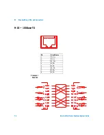
Page 75: ...74 Advisor Mainframe Features System Guide B Breakout Box LEDs and Connectors MDI 100Base TX Crossover Function Pin Circuit Name 1 TX_D1 2 TX_D1 3 RX_D2 4 BI_D3 5 BI_D3 6 RX_D2 7 BI_D4 8 BI_D4...

Page 76: ...75 Agilent Technologies C Regulatory Information Declarations of Conformity 76 Laser Safety Statements 110 Safety Information for Laser Source Modules 111...

Page 77: ...EEC including 93 68 EEC and carries the CE Marking accordingly European Union Against EMC test specifications EN 55011 1991 Group 1 Class A and EN 61326 1997 As detailed in Electromagnetic Compatibili...

Page 78: ...including 93 68 EEC and carries the CE Marking accordingly European Union Against EMC test specifications EN 55011 1991 Group 1 Class A and EN 61326 1997 As detailed in Electromagnetic Compatibility E...

Page 79: ...ements of the EMC Directive 89 336 EEC including 93 68 EEC and carries the CE Marking accordingly European Union Against EMC test specifications EN 55011 1991 Group 1 Class A and EN 61326 1997 As deta...

Page 80: ...and carries the CE Marking accordingly European Union Against EMC test specifications EN 55011 1991 Group 1 Class A and EN 61326 1997 As detailed in Electromagnetic Compatibility EMC Certificate of C...

Page 81: ...and carries the CE Marking accordingly European Union Against EMC test specifications EN 55011 1991 Group 1 Class A and EN 61326 1997 As detailed in Electromagnetic Compatibility EMC Certificate of C...

Page 82: ...the EMC Directive 89 336 EEC including 93 68 EEC and carries the CE Marking accordingly European Union Against EMC test specifications EN 55011 1991 Group 1 Class A and EN 61326 1997 As detailed in El...

Page 83: ...g 93 68 EEC and carries the CE Marking accordingly European Union Against EMC test specifications EN 55011 1991 Group 1 Class A and EN 61326 1997 As detailed in Electromagnetic Compatibility EMC Certi...

Page 84: ...g 93 68 EEC and carries the CE Marking accordingly European Union Against EMC test specifications EN 55011 1991 Group 1 Class A and EN 61326 1997 As detailed in Electromagnetic Compatibility EMC Certi...

Page 85: ...93 68 EEC and carries the CE Marking accordingly European Union Against EMC test specifications EN 55011 1991 Group 1 Class A and EN 61326 1997 As detailed in Electromagnetic Compatibility EMC Certifi...

Page 86: ...336 EEC including 93 68 EEC and carries the CE Marking accordingly European Union Against EMC test specifications EN 55011 1991 Group 1 Class A and EN 61326 1997 As detailed in Electromagnetic Compati...

Page 87: ...es the CE Marking accordingly European Union Against EMC test specifications EN 55011 1991 Group 1 Class A and EN 61326 1997 As detailed in Electromagnetic Compatibility EMC Certificate of Conformance...

Page 88: ...cal Construction File The product herewith complies with the requirements of the EMC Directive 89 336 EEC including 93 68 EEC and carries the CE Marking accordingly European Union Against EMC test spe...

Page 89: ...including 93 68 EEC and carries the CE Marking accordingly European Union Against EMC test specifications EN 55011 1991 Group 1 Class A and EN 61326 1997 As detailed in Electromagnetic Compatibility...

Page 90: ...uding 93 68 EEC and carries the CE Marking accordingly European Union Against EMC test specifications EN 55011 1991 Group 1 Class A and EN 61326 1997 As detailed in Electromagnetic Compatibility EMC C...

Page 91: ...luding 93 68 EEC and carries the CE Marking accordingly European Union Against EMC test specifications EN 55011 1991 Group 1 Class A and EN 61326 1997 As detailed in Electromagnetic Compatibility EMC...

Page 92: ...the CE Marking accordingly European Union Against EMC test specifications EN 55011 1991 Group 1 Class A and EN 61326 1997 As detailed in Electromagnetic Compatibility EMC Certificate of Conformance Re...

Page 93: ...the CE Marking accordingly European Union Against EMC test specifications EN 55011 1991 Group 1 Class A and EN 61326 1997 As detailed in Electromagnetic Compatibility EMC Certificate of Conformance Re...

Page 94: ...luding 93 68 EEC and carries the CE Marking accordingly European Union Against EMC test specifications EN 55011 1991 Group 1 Class A and EN 61326 1997 As detailed in Electromagnetic Compatibility EMC...

Page 95: ...luding 93 68 EEC and carries the CE Marking accordingly European Union Against EMC test specifications EN 55011 1991 Group 1 Class A and EN 61326 1997 As detailed in Electromagnetic Compatibility EMC...

Page 96: ...ding 93 68 EEC and carries the CE Marking accordingly European Union Against EMC test specifications EN 55011 1991 Group 1 Class A and EN 61326 1997 As detailed in Electromagnetic Compatibility EMC Ce...

Page 97: ...EC including 93 68 EEC and carries the CE Marking accordingly European Union Against EMC test specifications EN 55011 1991 Group 1 Class A and EN 61326 1997 As detailed in Electromagnetic Compatibilit...

Page 98: ...EC including 93 68 EEC and carries the CE Marking accordingly European Union Against EMC test specifications EN 55011 1991 Group 1 Class A and EN 61326 1997 As detailed in Electromagnetic Compatibilit...

Page 99: ...3 68 EEC and carries the CE Marking accordingly European Union Against EMC test specifications EN 55011 1991 Group 1 Class A and EN 61326 1997 As detailed in Electromagnetic Compatibility EMC Certific...

Page 100: ...3 68 EEC and carries the CE Marking accordingly European Union Against EMC test specifications EN 55011 1991 Group 1 Class A and EN 61326 1997 As detailed in Electromagnetic Compatibility EMC Certific...

Page 101: ...EEC including 93 68 EEC and carries the CE Marking accordingly European Union Against EMC test specifications EN 55011 1991 Group 1 Class A and EN 61326 1997 As detailed in Electromagnetic Compatibil...

Page 102: ...336 EEC including 93 68 EEC and carries the CE Marking accordingly European Union Against EMC test specifications EN 55011 1991 Group 1 Class A and EN 61326 1997 As detailed in Electromagnetic Compat...

Page 103: ...336 EEC including 93 68 EEC and carries the CE Marking accordingly European Union Against EMC test specifications EN 55011 1991 Group 1 Class A and EN 61326 1997 As detailed in Electromagnetic Compat...

Page 104: ...ng 93 68 EEC and carries the CE Marking accordingly European Union Against EMC test specifications EN 55011 1991 Group 1 Class A and EN 61326 1997 As detailed in Electromagnetic Compatibility EMC Cert...

Page 105: ...ng 93 68 EEC and carries the CE Marking accordingly European Union Against EMC test specifications EN 55011 1991 Group 1 Class A and EN 61326 1997 As detailed in Electromagnetic Compatibility EMC Cert...

Page 106: ...including 93 68 EEC and carries the CE Marking accordingly European Union Against EMC test specifications EN 55011 1991 Group 1 Class A and EN 61326 1997 As detailed in Electromagnetic Compatibility...

Page 107: ...ing 93 68 EEC and carries the CE Marking accordingly European Union Against EMC test specifications EN 55011 1991 Group 1 Class A and EN 61326 1997 As detailed in Electromagnetic Compatibility EMC Cer...

Page 108: ...3 68 EEC and carries the CE Marking accordingly European Union Against EMC test specifications EN 55011 1991 Group 1 Class A and EN 61326 1997 As detailed in Electromagnetic Compatibility EMC Certific...

Page 109: ...complies with the requirements of the EMC Directive 89 336 EEC including 93 68 EEC and carries the CE Marking accordingly European Union Against EMC test specifications EN 55011 1991 Group 1 Class A a...

Page 110: ...product standards EMC Standard IEC 61326 1 1997 A1 1998 EN 61326 1 1997 A1 1998 CISPR 16 1 1993 CISPR 16 2 1996 IEC 61000 4 2 1995 A1 1998 EN 61000 4 2 1995 IEC 61000 4 3 1995 EN 61000 4 3 1995 IEC 6...

Page 111: ...ety Statements Some Advisor interfaces contain Class 1 laser devices Class 1 laser devices are considered to be safe based upon current medical knowledge A laser safety warning label is attached to th...

Page 112: ...1 Transmitter Min Typical Max Avg Optical Power dBm 10 0 7 5 4 0 Optical Wavelength nm 830 845 860 Receiver Min Typical Max Optical Sensitivity dBm l 19 0 17 0 Peak Input Power dBm l l 0 Optical Wavel...

Page 113: ...tical Power dBm 12 0 10 0 5 0 Optical Wavelength nm 1260 1310 1360 Receiver Min Typical Max Optical Sensitivity dBm 28 0 32 0 l Peak Input Power dBm l l 3 0 Optical Wavelength nm 1240 l 1650 WARNING Y...

Page 114: ...ypical Max Avg Optical Power dBm 15 13 8 Optical Wavelength nm 1293 1310 1334 Receiver Min Typical Max Optical Sensitivity dBm 28 30 l Peak Input Power dBm l l 3 Optical Wavelength nm 1200 l 1550 WARN...

Page 115: ...114 Advisor Mainframe Features System Guide C Regulatory Information...

Page 116: ...2300E 80 J2306B J2309B 81 J2307A 82 J2524A 83 J2527A 84 J2900A 85 J2901A 86 J2904B 87 J2905B 88 J2908A 89 J2909A 90 J2912A 91 J2912B 92 J2913A 93 J2913B 94 J2914A 95 J3444A 96 J3445A 97 J3446D 98 J344...

Page 117: ...keyboard 58 keypad 60 LED 60 L lateral switch bank 62 LED lights active interface LEDs 64 Lead status LEDs 65 Mark LEDs 63 RS 232 V 24 64 RS 449 64 Space LEDs 63 System LEDs 62 T1 E1 64 V 35 64 LEDs...

Page 118: ...switches breakout box switches 62 DTE switch 63 lateral switch bank 62 vertical switch bank 62 System LEDs 62 T terminal generated control signals 62 tests RS 232 test connector 62 RS 232 V 24 test c...

Page 119: ...118 Advisor Mainframe Features System Guide Index...

Page 120: ...uipment Have surplus equipment taking up shelf space We ll give it a new home Learn more Visit us at artisantg com for more info on price quotes drivers technical specifications manuals and documentat...

Reviews: