2
General Power Meter Functions
72
N1913/1914A EPM Series Power Meters User’s Guide
Recorder Output
The rear panel
Recorder Output
connectors (1 and 2) produce a dc
voltage that corresponds to the power level in Watts of the selected
measurement window. This dc voltage ranges from 0 to +1 Vdc. The output
impedance is typically 1 k
Ω
.
For example, the Recorder Outputs can be used to:
• Record swept measurements
• Level an output from a source using external leveling, or
• Monitor the output power
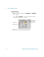
To access the
Recorder
menu press
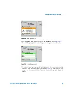
, and enable Rec o/p. This
allows you to switch the Recorder Output signal on or off and set the
scaling of power levels automatically or manually. The
and
softkeys allow you to manually scale the power levels to
represent the 1 Vdc maximum and 0 Vdc minimum output voltage of the
Recorder Output. Otherwise, you can set the Recorder Output to
Auto
to
enable auto- scaling.
In auto- scaling, the minimum power is fixed at –150 dBm and the
maximum power is automatically scaled based on the current power level.
The auto- scaled maximum power ranges from –140 dBm, steps every 10
dBm until +230 dBm depending on the current power level. The
auto- scaling is not applicable if the measurement of the selected window
is a difference, ratio, channel C, or D measurement.
Procedure
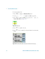
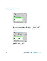
Set the recorder output as follows:
1
Press
,
to display the
Measurement Setup
menus.
2
Use the
and
keys to highlight the
Rec o/p:
setting field.
Max Power
Min Power
N O T E
Ensure you have selected the channel you want to set up.
Meas Select

