6
Using N8480 Series Power Sensors
148
N1913/1914A EPM Series Power Meters User’s Guide
Introduction
The N8480 Series power sensors are replacement for the 8480 Series power
sensors (excluding the D- model sensors) with build- in
E
lectrically
E
rasable
P
rogrammable
R
ead-
O
nly
M
emory
(
EEPROM)
1
.
The N8480 Series power sensors are used for measuring the average power
supplied by RF or microwave source or a device- under- test (DUT). The N8480
Series power sensors place a 50
Ω
load on the RF or microwave source. The
power meter indicates the power dissipated in this load in W or dBm.
The N8480 sensors (excluding Option CFT) measure power levels from –35
dBm to +20 dBm (316 nW to 100 mW), at frequencies from 10 MHz to 33
GHz and have two independent power measurement path (upper and lower
range).
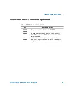
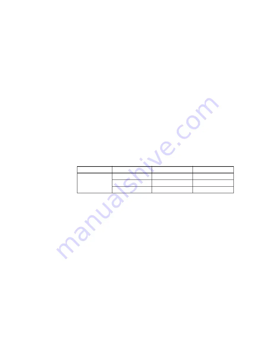
Table 6-1
Power range in the Range setting
Meanwhile, the N8480 sensors with Option CFT only measure power levels
from –30 dBm to +20 dBm (1 µW to 100 mW) in single range.
Similar to the E- Series power sensors, the N8480 Series power sensors are
also equipped with EEPROM to store sensor’s characteristics such as model
number, serial number, linearity, temperature compensation, calibration
factor
1
and so forth. However, the calibration factor table stored in EEPROM
is not applicable for N8480 Series power sensors with Option CFT, and
require that you use default calibration tables or manually enter the required
correction factors. Likewise, they cannot be used to make peak or time gated
measurements.
Please refer to the documentation supplied with your Agilent N8480 Series
power sensors for specification and calibration information.
1
The calibration factor table stored in the EEPROM is not applicable for N8480 Series sensors with
Option CFT.
2
Recommended for pulse signals measurement with period of more than one second.
Sensor
Range Setting
Lower Range
Upper Range
N8481/2/5/7/8A
excluding Option CFT
AUTO (Default)
–35 dBm to –1 dBm
–1 dBm to +20 dBm
LOWER
–35 dBm to –1 dBm
-
UPPER
2
-
–30 dBm to +20 dBm

