N4962A System Overview
Serial BERT 12.5 Gb/s User Guide
17
2
N4962A System Overview
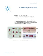
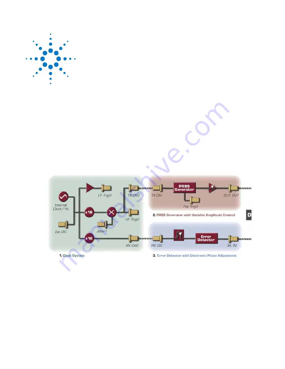
The N4962A consists of three functional blocks:
•
Internal/external clock system with analog jitter injection
•
PRBS generator (TX) with variable output amplitude control
•
Error detector (RX) with electronic clock phase adjustment
The N4962A is controlled by front-panel buttons and remote GPIB (IEEE
488.2) commands; information is conveyed with LED indicators and a display
on the front panel, along with GPIB data communication.
Figure 2. N4962A simplified block diagram; system overview
Summary of Contents for N4962A
Page 1: ...Agilent N4962A Serial BERT 12 5 Gb s User Guide...
Page 6: ......
Page 16: ...Getting Started 16 Serial BERT 12 5 Gb s User Guide...
Page 24: ...N4962A System Overview 24 Serial BERT 12 5 Gb s User Guide...
Page 36: ...System Details and Performance Specifications 36 Serial BERT 12 5 Gb s User Guide...
Page 60: ...Operation 60 Serial BERT 12 5 Gb s User Guide...
Page 86: ...Remote GPIB Interface 86 Serial BERT 12 5 Gb s User Guide...
Page 88: ...Copyright Agilent Technologies 2012 Third edition May 2013 Printed in Germany...


