Operation
56
Serial BERT 12.5 Gb/s User Guide
4.5.4
Low BER Test
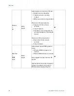
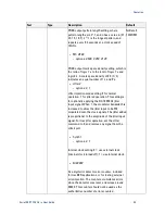
To verify that the error detector can correctly count a small number of errors,
use the PRBS error injection capability to insert a known number of errors into
the bit stream, as follows:
•
Put the system in self test mode, described in Section 4.5.1.
•
Press the Display > Scroll
↓ button and select
ErAd OFF
•
Press the Adjust > Config State + button and select ErAd 1E0
•
Press the Receiver > On button and ensure the light is on
•
Observe the
Error ε
light (should blink once per second)
•
Press the Display > Scroll
↑
button and select Err (should show 1 per
second)
•
Press the Display > Scroll
↓
button and select BER (should show
1E-10)
•
Press the Display >
Scroll ↓
button and select
ε time (sec)
(should be
increasing)
4.6
BER Detector Clock Phase Adjustment
The error detector clock phase can be electronically controlled to adjust the
detector sampling point; the periodic point at which the detector interprets the
incoming bit stream. Due to the unknown delay associated with cables and the
DUT in the data path, the incoming bit stream may not be sampled at the
optimal point.
The detector must be adjusted to find the optimal sampling point; an incorrect
sampling point will yield an artificially-high BER measurement, shown in Figure
14.
Summary of Contents for N4962A
Page 1: ...Agilent N4962A Serial BERT 12 5 Gb s User Guide...
Page 6: ......
Page 16: ...Getting Started 16 Serial BERT 12 5 Gb s User Guide...
Page 24: ...N4962A System Overview 24 Serial BERT 12 5 Gb s User Guide...
Page 36: ...System Details and Performance Specifications 36 Serial BERT 12 5 Gb s User Guide...
Page 60: ...Operation 60 Serial BERT 12 5 Gb s User Guide...
Page 86: ...Remote GPIB Interface 86 Serial BERT 12 5 Gb s User Guide...
Page 88: ...Copyright Agilent Technologies 2012 Third edition May 2013 Printed in Germany...

