20
N9320B Spectrum Analyzer
2
N9320B Overview
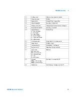
Rear Panel Overview
1
REF OUT connector
provides a frequency of 10 MHz, amplitude
of –10 dBm reference output. (BNC female)
2
REF IN connector
accepts an external timebase with a
frequency of 10 MHz, amplitude of –5 to +10 dBm. (BNC
female)
3
Kensington Lock
lock the instrument and keep its safety.
4
LAN
port
A TCP/IP Interface that is used for remote
analyzer operation.
5
EXT TRG IN (TTL) connector
accepts an external voltage input,
the positive edge of which triggers the analyzer sweep
function. (BNC female)
6
Power switch
isolates the analyzer from the AC line power.
After switch on, the analyzer enters into standby mode and
the orange standby LED on the front panel lights.
7
AC Power Receptacle
accepts a three- pin line power plug.
8
VGA connector
provides the video output signal to an
external monitor or projector. (D- sub 15- pin female)
9
USB Host connector
provides a connection between the
analyzer and an PC for remote control.
REF IN
REF OUT
TRIG IN
USB
LAN
VGA
OUT
T
T
L
~100-240
V
50-60
Hz
100
W MAX
SERIAL LABEL
ATTACH HERE
HIPOT LABEL
ATTACH HERE
10MHz
10MHz
1
2
9
4
5
6
7
8
3


