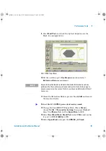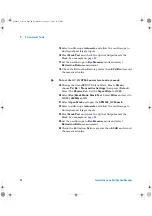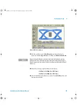
98
Installation and Verification Manual
3
Performance Tests
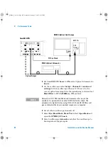
Equipment Required
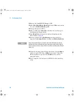
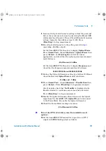
1
Press
<Menu>
, choose
Tx/Rx > Stored Settings
then press
<Select>
. Select
Default
then
Recall
.
2
Press
<Menu>
, choose
Tx/Rx > Coupling
then press
<Select>
. Select
Copy Tx to Rx
.
N O T E
•
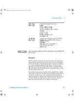
These tests are identical for SONET or SDH modes and can be tested in either
mode and should not be repeated for both.
•
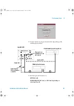
Always set the Laser to OFF before changing Optical Output Port connections.
•
It is most important that advice on Optical Cleanliness is adhered to ensure
accuracy of these tests and to prevent damage to optical interfaces
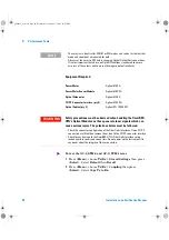
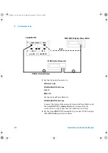
Power Meter
Agilent 8163A
Power Meter Sensor Module
Agilent 81633A
Optical Attenuator
Agilent 8156A
FC/PC Connector Interface (qty 4)
Agilent 81000FI
Optical Cables (qty 2)
Agilent PN 1005-0337
WA R N I N G
Safety precautions must be observed when handling the OmniBER
OTN’s Optical Modules as these generate laser signals which can
cause serious injury. The guidelines below must be followed:
•
Check the connector configuration of the Fiber Optic Interfaces. If non FC/PC
connectors are fitted then remove them, then fit the FC/PC connector interface.
•
Check for any damage to the OmniBER OTN’s Fiber Optic Interface spring
loaded aperture covers and connectors. Do not power up the instrument if in
any doubt about the integrity of these connectors.
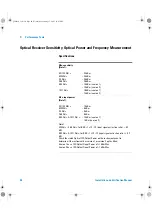
To test the OC-1/STM-0 and OC-3/STM-1 rates
panther3_iv.book Page 98 Wednesday, January 15, 2003 12:03 PM

