22
Installation Note
E4440-90632
Installation Procedure
CAUTION
In the following step, use a 5/16 inch wrench on the attenuator to
prevent the attenuator from rotating when installing the cable. The
attenuator can be damaged if it is allowed to rotate when loosening or
tightening the cable connector.
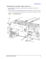
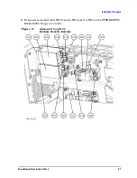
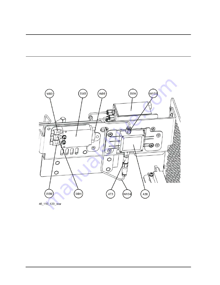
18. Refer to
. Locate semi-rigid cable W104 (
) from the kit. Install
this cable from the attenuator on the preamplifier output through the main bracket to
switch SW4 port 3. Torque to 10 in-lb.
Figure 18
Options 110 and 123
E4446A, E4447A, E4448A (Rear View)
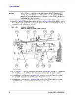
. Locate semi-rigid cable W103 (
) from the kit. Install
this cable from switch SW4 port 2 to the preamplifier input. Torque to 10 in-lb.
20.Locate semi-rigid cable W102 (
) from the kit. Install this cable from
Attenuator B output to switch SW4 port 1. Torque to 10 in-lb.
21.Locate semi-rigid cable W101 (
) from the kit. Install this cable from
switch SW4 port 4 to switch SW5 port 1. Torque to 10 in-lb.

